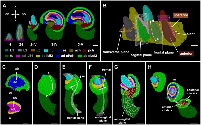
Figure 2.
Developmental axes in ovule development. A, Mid-sagittal sections through 3D digital ovules of representative stages. The individual images were digitally extracted for comparison. The different tissues are indicated as are the anterior–posterior and proximal–distal axes, respectively. Staging according to Schneitz et al. (1995) and Vijayan et al. (2021). B, 3D rendering of a placenta area carrying seven wild-type Stage 2-I ovules. The anterior–posterior and proximal–distal axes are marked. The sagittal, transverse, and frontal planes are marked by grids on the primordia. The frontal plane separates the anterior and posterior halves of the organ. The sagittal plane separates the left and right half of the organ. The dashed white arrow indicates the proximal–distal axis. Anterior and posterior side of the organ is highlighted with different colors in two of the representative ovules showing the sagittal and the frontal grid. Black dotted line indicates the placental surface to which the posterior side of the ovule is slanted with a small angle. C, Outer and inner integument tissues extracted from the 3D mesh for visualizing the abaxial–adaxial polarity. Tilted view of mid-sagittal sections through the outer and inner integument, respectively, of a Stage 3-IV 3D digital ovule. The arrows highlight the adaxial–abaxial axes of each integument. D–H, Visualization of different tissues in a Stage 2-V Arabidopsis ovules at different orientations of the organ. D, Posterior view of the ovule with the proximal–distal axis of the outer integument marked. E, Side view (left) and anterior view (right). Grid represents the frontal plane. The medio-lateral axis is indicated. F, Anterior view of the ovule visualizing the frontal region. The grid represents the mid-sagittal plane. G, A mid-sagittal section view of the ovule in (F) visualizing the maximal proximal–distal extension of the integuments. H, A 3D clipped view of the 3D digital ovule is displayed. It is oriented with the posterior side to the right. The 3D view allows the discrimination of the left-right sides of the 3D digital ovule. The dashed line indicates the medial line. an, anterior; ab, abaxial; ad, adaxial; ach, anterior chalaza; ch, chalaza; d, distal; ii, inner integument; es, embryo sac; fu, funiculus; l, lateral; le, left; m, medial; nu, nucellus; oi, outer integument; p, proximal; pch, posterior chalaza; po, posterior; ri, right. Scale bars: 20 µm.

