
Figure 1.
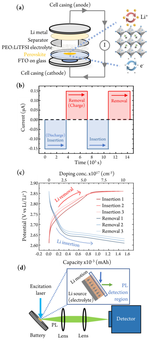
Controlled doping of a halide perovskite using a battery-inspired device architecture. (a) Schematic representation of the battery device stack used. Abbreviations: PEO, poly(ethylene oxide); LiTFSI, lithium bistrifluoromethanesulfonylimide; FTO, fluorine-doped tin oxide. (b) Applied current and cycling time during galvanostatic battery discharge (Li+ + e– insertion) and charge (removal) cycles. (c) Galvanostatic charge–discharge curves of the LIB device showing three Li insertion and removal processes and the equivalent doping concentration after each step. (d) In situ photoluminescence (PL) spectroscopy setup to probe the battery at different charge doping states. Inset: schematic showing the PL detection region at the rear side of the perovskite relative to the Li insertion interface.