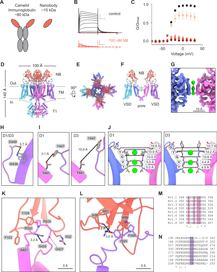
Fig. 3. Multiple nanobodies bind the turret loops and voltage sensing domains of Kv1.3.
A Illustration of camelid antibody and nanobody. B Kv1.3 current traces obtained from a family of depolarizing pulses ranging from −80 mV to +30 mV in control 2 mM K+ solutions (black) and in the presence of 100 nM nanobody (NB) A0194009G09 (orange). Holding voltage was −80 mV and tail voltage was −50 mV. Red dotted line denotes zero current level. Scale bars indicates 2 μA and 50 ms. C G-V relations obtained in control 2 mM K+ solutions (black squares; n = 20), 1 nM (right facing triangles, light orange; n = 7), 10 nM (upright triangles, pink; n = 3), 100 nM (circles, orange; n = 7) or 1 µM nanobody (diamonds, dark red; n = 3) by measuring the peak of the tail current at −50 mV and normalizing it to the maximum tail current in control solution. Error bars are SEM. Side (D) and extracellular (E) views of the model for Kv1.3 in complex with four nanobodies (orange). F Cutaway view of the structure in (D) showing two nanobodies with each bound to a pore domain and a VSD of Kv1.3. The T1 domains are omitted for clarity. G Cryo-EM density of the pore region (C1 symmetry). H, I Views of W436/D449 and T441/Y447 for both the D1 and D3 conformations identified in the Kv1.3-nanobody structure. J Structures of the selectivity filter of the Kv1.3-nanobody complex with the D1 (left) and D3 (right) conformations. Distances between carbonyl oxygens of the TVGYG motif are reported and marked with black lines. K+ ions shown in green. Close up views of a nanobody in complex with a turret loop of a pore domain (K) and the S1-S2 loop of a VSD (L). Sequence alignment for the turret loop (M) and VSD S1-S2 loop (N) regions for human Kv1 channels. Source data are provided as a Source Data file.

