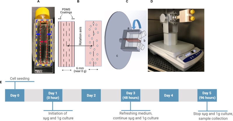
Fig. 1. Experimental setup to simulate microgravity.
A Clipmax chamber-slide flask with a small cell culture channel created (represented by a red double-sided arrow) after filling the two sides (represented by two blue double-sided arrows) and the top of the chamber-slide flask (not shown) with PDMS. B Distribution of microgravity forces in relation to the rotation axis at the area where cells are cultured. Oval circles represent cells. C Illustration of the developed device to simulate microgravity: (A) indicates 3-D printed adapter connecting two cell culture flasks (B) to the spinning bolt of a sample rotator instrument. C Indicates the bottom surfaces of the flasks where cells are attached (illustrated in red), which are positioned back-to-back and located in the axis of rotation. D Our developed rotary cell culture system (RCCS) with 2 flasks affixed to the system and located inside of the cell culture incubator, ready to generate simulated microgravity. E Experimental design used in this project.

