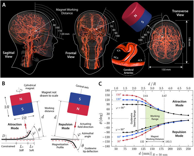
Figure 3. Design considerations for magnetic steering with a single magnet.
(A) Working distance and area for a cylindrical magnet (diameter and thickness of 100 mm) around the head considering the average head size (22) and anatomical location and orientation of intracranial arteries illustrated on the sagittal, frontal, and transverse planes. When viewed from the sagittal plane, the distance from the surface of the magnet to the Circle of Willis in the middle of the head is estimated to be around 100 mm. When viewed from the frontal and transverse planes, the distance from the surface of the magnet to left ICA bifurcation is estimated to be 80~90 mm. ICA: internal carotid artery; MCA/ACA: middle/anterior cerebral artery. (B) Attraction and repulsion modes for steering control of the magnetic guidewire with a single magnet of cylindrical shape (diameter and thickness of 2R). The magnet working distance, denoted d, is defined as the distance from the center of the magnet to the base of the guidewire’s softer tip. The angular position of the magnet relative to the guidewire’s reference state is defined by the azimuthal angle φ, and the tip deflection angle is denoted θ. D indicates the outer diameter of the guidewire, and L1 and L2 denote the stiff and soft segments in the unconstrained (free to bend) portion of the guidewire’s steerable tip, respectively. (C) Characterization of the magnetic guidewire’s behavior under magnetic manipulation with a single magnet. The tip deflection angle θ was measured while varying the working distance and the angular position of the actuating magnet in the attraction and repulsion modes (guidewire dimension: D = 400 μm, L1 = 6 mm, L2 = 4 mm).

