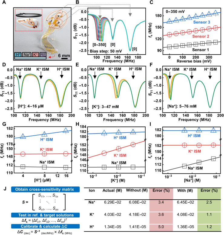
Fig. 5. Multiplexed sensor system based on the LC circuit and sensing performance in mixed ion solutions.
(A) Photograph of a multiplexed ion sensor system consisting of three LC circuits with varied resonance frequency. The four electrodes (from left to right) correspond to H+, Na+, and K+ sensors and the RE. (B) Resonance curves of the multiplexed sensor array with a reverse DC bias applied to one LC circuit. (C) Response to input DC voltage of the three sensors in the multiplexed sensing platform. (D to F) Resonance curves of the multiplexed sensing system in response to concentration change in H+, K+, and Na+ in the mixed ion solution. (G to I) Extracted cross-sensitivity of the multiplexed sensing system based on results in (D) to (F). (J) Calibration methodology used for the multiplexed sensor arrays and calculated ion concentrations in a mixed ion test solution obtained without and with calibration.

