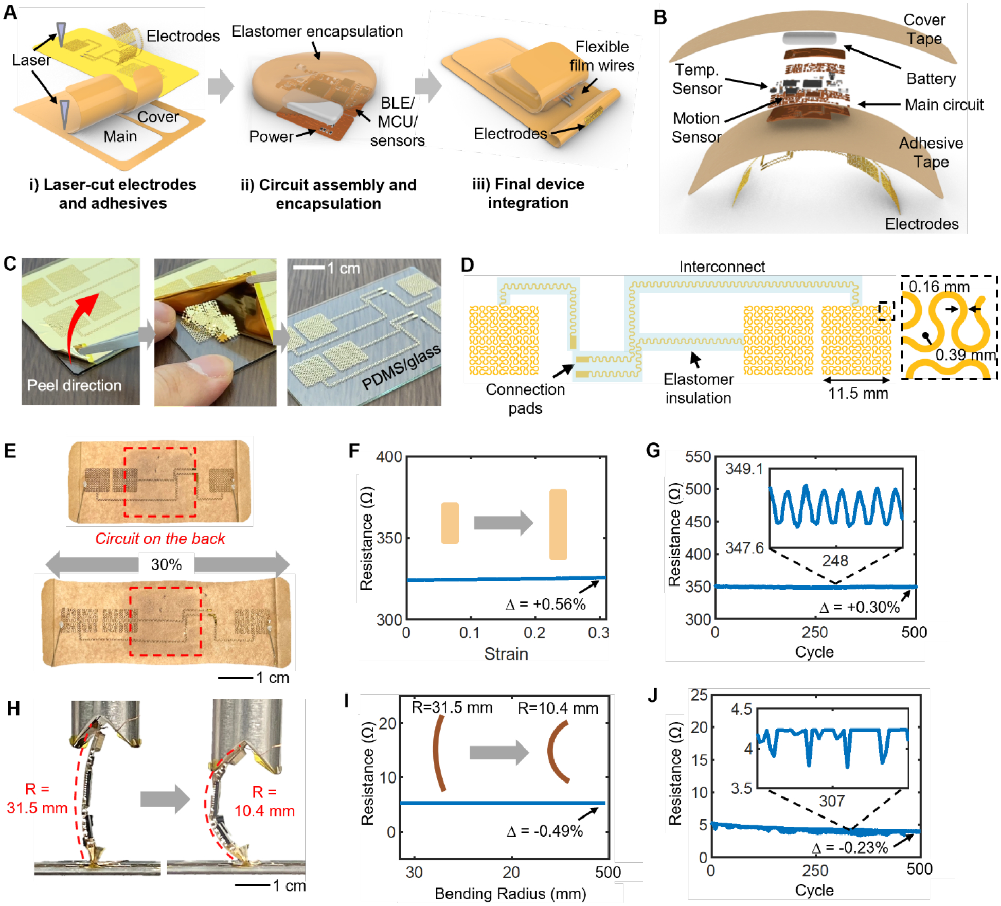
Figure 2. Fabrication of a biopatch and mechanical reliability.

(A) Schematic illustration of the three main steps involved with biopatch assembly. (B) Blowup render of the biopatch detailing the stacking order of various components. (C) Single-step removal of the non-functional region of the laser-cut film and leaving the functional electrodes. (D) Drawing of the electrode-interconnect showing the serpentine traces and areas insulated with an elastomer. (E) Experimental validation of the maximum stretchability of the electrodes. (F–G) Measured resistance across the two furthermost electrodes during full stretching (F) and cyclic stretching (G). Relative values of resistance (Δ) show negligible changes. (H) Experimental bending analysis for the wireless circuit (R=radius of curvature). (I–J) Measured resistance across two furthermost points on the circuit’s ground node during maximum bending (I) and cyclical bending (J) tests.
