
Fig. 1 |. Three- and four-helix bundles.
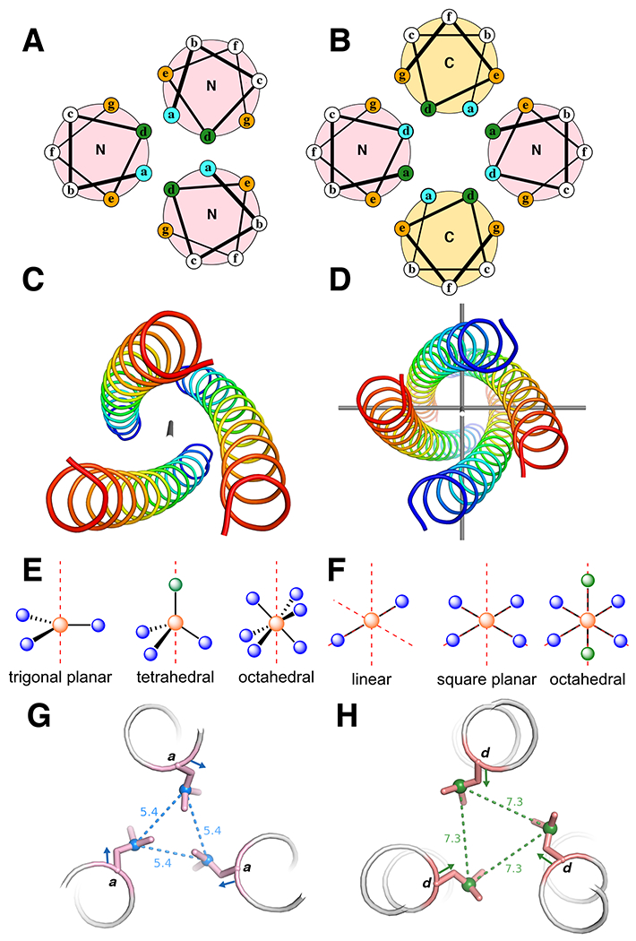
a | Helical wheel diagrams of parallel three-helix bundles. N and C are the terminal ends of the helices. b | Helical wheel diagrams of anti-parallel four-helix bundles. a and b show the heptad arrangements. The buried residues (green and blue) are packed against each other in the core, the orange positions are at the helical interface, and the white positions are on the surface. The N (blue) and C (red) termini of each helix are labelled to show directionality. c |A parallel three-helix bundle with idealized C3-symmetry. The axis of symmetry (in gray) traverses the center of the bundle. d |An antiparallel four-helix bundle with idealized D2-symmetry. The three axes of C2-symmetry are shown in gray. e, f |Examples of idealized coordination geometries accessible in e C3-symmetric three helix bundles and f D2-symmetric four helix bundles. The red axes represent the rotational symmetry axes. Orange spheres are the metal ions, blue spheres are coordinating ligands, and green spheres are empty coordination sites. g, h |Illustration of the difference between an a- g and a d-position h with respect to sidechain orientation. The coloured vector indicates the Cα-Cβ bond direction and the dashed lines and distances (Å) indicate the Cγ-Cγ’ vector.