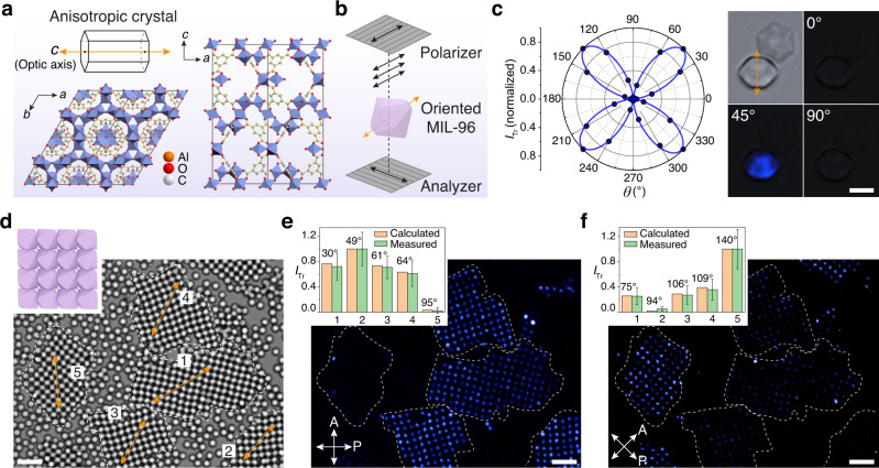
Fig. 6. Birefringent 2D films of anisotropic MIL-96.
a Molecular structure of MIL-96 along c and b axes (a-b plane and a-c plane). The optic axis (c axis) is shown by orange double arrow. Orange, red, and gray spheres represent aluminum, oxygen, and carbon atoms, respectively. Al octahedra are shown in blue. b Observation of birefringence using polarized light microscopy with crossed polarizer/analyzer (gray grating). The black double arrows show the polarization direction after light passes through the polarizer or analyzer. The transmission light intensity (ITr) is recorded every 15° by rotating the crossed polarizer/analyzer pair. c Plot with fitting of the normalized ITr as a function of θ, angle between light polarization and MOF’s optic axis (projected on x–y plane). Bright-field and polarized optical images of 5.1-µm MIL-96 particles at θ = 0, 45, and 90°. MIL-96 particle standing by its (101) face exhibits typical birefringence of a uniaxial crystal; the one standing by the (002) face is always dark. d Bright-field optical image and cartoon of MIL-96 films assembled from 1.8-µm particles. The superlattice grains are circled by dotted line and labeled by their orientation (orange double arrows). e, f Crossed-polarized microscope images show birefringence of the superlattice grains in (d) at polarization angles of 0° (e) and 45° (f). Angle of each crystal grain with respect to polarization direction is measured and the theoretical intensities are calculated, which agree with the measured ITr (normalized) values (charts, insets). Scale bars: 3 µm (c) and 5 µm (d–f).

