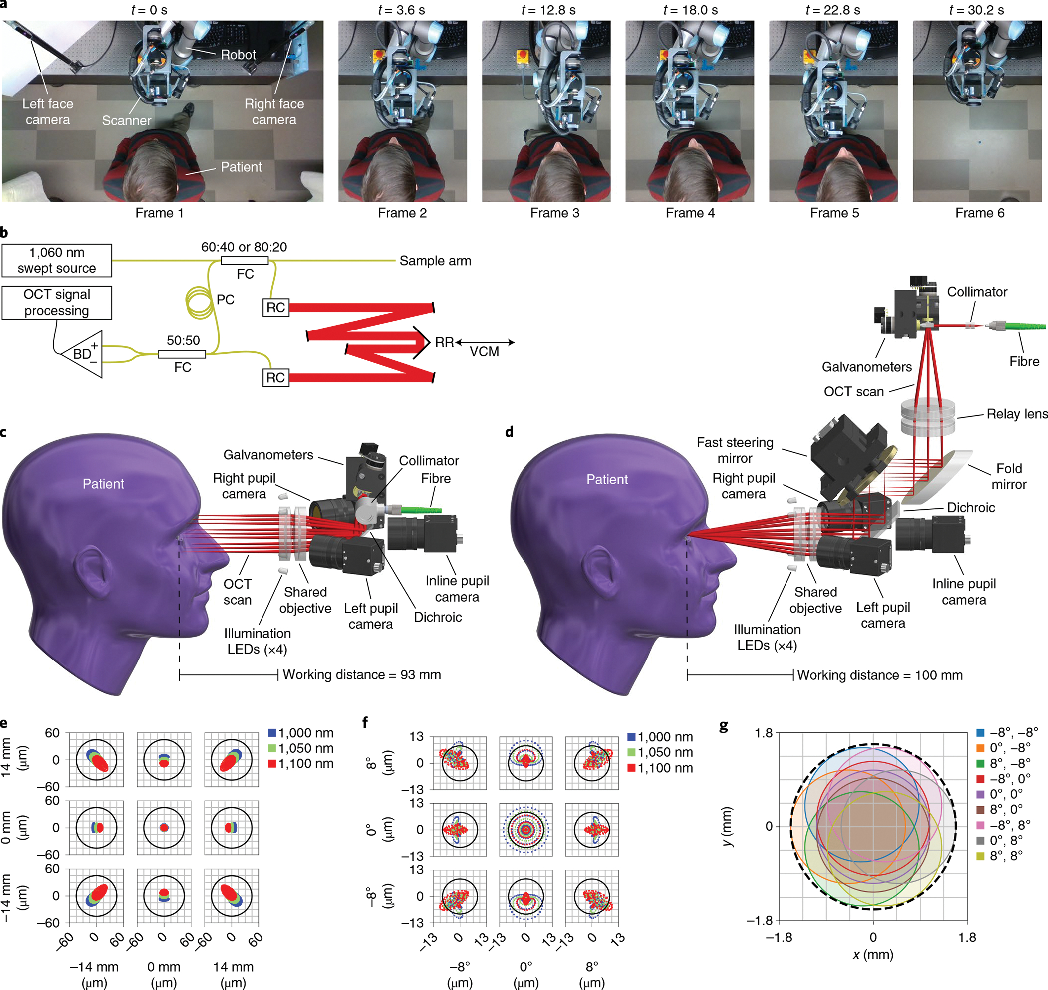
Fig. 1 |. OCt system and scan heads for active tracking.

a, Robotic scanner positioning to approach the patient, align with the right (frames 2 and 3) and left (frames 4 and 5) eyes, and retract once done (frame 6). Images show a top-down view of the robot’s workspace during the imaging session in sequence from left to right. The robot arm follows the patient to keep the eye centred within the working range for optical active tracking (Supplementary Video 1). b, OCT engine with Mach–Zehnder topology, transmissive reference arm with adjustable length, and balanced detection. The retroreflector is mounted on the voice coil motor (VCM) to provide high-frequency compensation in path length for axial active tracking. BD, balanced detector; FC, fibre coupler; PC, polarization controller; RC, reflective collimator; RR, retroreflector; black lines, electrical wires; yellow lines, optical fibre; red lines, free-space optical path of reference arm. c, Anterior scan head model with optical ray trace, showing a telecentric scan with a 93 mm working distance. Lateral active tracking is achieved by altering the galvanometer scan angles, which shifts the scan laterally. LEDs, light-emitting diodes. d, Retinal scan head model with optical ray trace, showing a 4f retinal telescope with a 100 mm working distance. Lateral active tracking is achieved by tilting the FSM located in the telescope’s Fourier plane, such that tilt manifests as lateral translation at the pupil pivot. The scan pattern completely fills the objective so galvanometer scan angles remain fixed despite tracking. e, Anterior scan head optical spot diagram for the three design wavelengths over a ±14 mm scan, indicating diffraction-limited performance. The Airy radius is 43 μm. f, Retinal scan head optical spot diagram for the three design wavelengths over a ±8° scan, indicating nearly diffraction-limited performance due to residual spherical aberration. The Airy radius is 8.5 μm for the entrance beam diameter of 2.5 mm. g, Retinal scan head pupil wobble diagram indicating minimum acceptable diameter of 3.2 mm (dashed black line).
