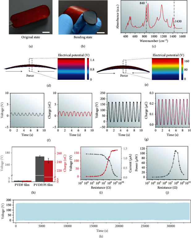
Figure 2.

Characterization of the i-PENG. Photographs of the (a) original and (b) bent i-PENG demonstrating its good flexibility (scale bar = 1 cm). (c) Fourier transform infrared spectra of the PVDF film. Finite-element simulation of the voltage potential distribution for (d) the pure PVDF film and (e) the PVDF film integrated with the PI substrate. VOC and QSC of (f) the pure PVDF film and (g) the PVDF film integrated with the PI substrate. These two different structure devices are driven by linear motors with a frequency of 1 Hz. (h) Statistical comparison of average VOC and QSC of the pure PVDF film and the PVDF film integrated with the PI substrate. (i) VOC, ISC, and (j) peak power of the i-PENG at different load resistances. (k) Fatigue test of the i-PENG (~33,750 s, at 2 Hz).
