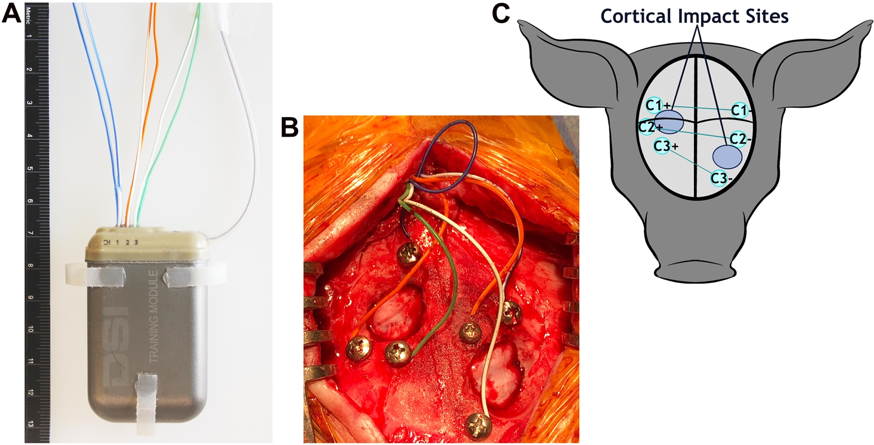
Figure 2.

EEG implant and montage. A, The 59 × 38 × 15 mm EEG transmitter with electrodes exiting the top of the implant, the antennae projecting off the right of the implant, and tabs on the sides and bottom that are used to suture the implant in place. B, Pigs received bilateral cortical impact through the burr holes. The electrode array before the application of dental cement. C, A schematic of the three-channel bipolar montage with electrode sites (teal circles) centered around the sites of cortical impact (large blue circles). Black lines represent the sagittal and coronal sutures.
