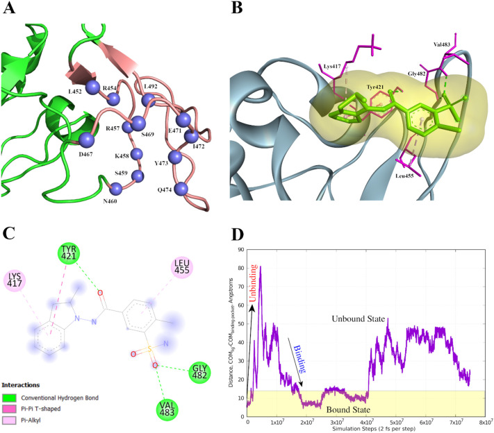
Fig. 7.
Representation of proposed lead molecule binding sites in RBD and its interaction with the therapeutic lead. (A) Blue spheres indicate the residues (of SB10) predicted as binding sites. The tv_red region indicates rest of the residues of SB10. The rest part of the RBD is represented in forestgreen. (B) R-Indapamide bound RBD where R-Indapamide is shown by green sticks with a pale orange surface around it. Its interactions with RBD has been represented as sticks (magenta) while rest of the protein is represented as slate blue. (C) 2D representation of docked complex which indicates the interacting residues. (D) Evolution of reaction coordinate during the metadynamics trajectory. Plot showing unbinding and binding events during the metadynamics simulation. The simulation protocol ensures that the system samples both unbound and bound configurations to compute the relative free energies of both configurations. (For interpretation of the references to colour in this figure legend, the reader is referred to the web version of this article.)

