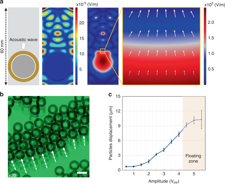
Fig. 2. Acoustofluidic particle manipulation for 2D scanning.
a Left: Schematic of the acoustofluidic device consisting of a circular shaped piezoelectric transducer with a glass cover slip. a Middle: Simulation result of the acoustic pressure on the bottom surface of the acoustofluidic device. a Right: Simulation result of the acoustic pressure within the water medium below the glass. The small orange box indicates the formation of an acoustic streaming point to uniformly push the microspheres. b Microsphere particle movement as a function of input acoustic amplitude applied with a 2.1 kHz wave at a 0.2 s burst interval. The scale bar is 20 µm. c Particle displacement distance with a given applied amplitude. At an amplitude of 4.5 VPP and higher (orange area), microspheres were observed to float in suspension. N = 100 tracked particles, and the error bars represent the standard deviation.

