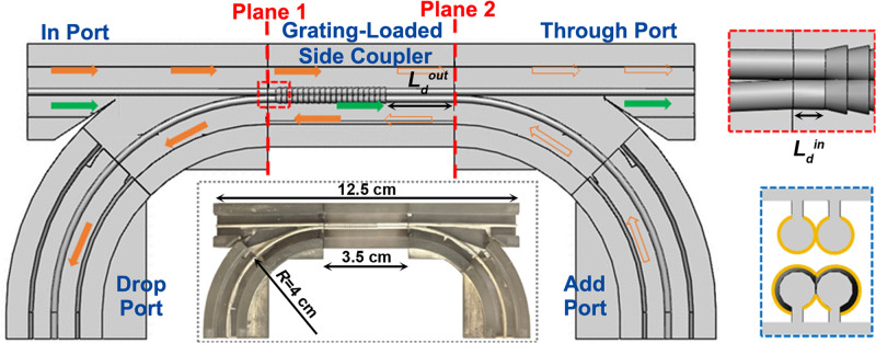
Fig. 1. Schematic of the four-port ADM circuit comprising a grating-loaded side coupler placed between two Y-splitters.
Ldin and Ldout are the distances between the grating and the directional coupler end-facets (see an Insert in the red dotted box). The solid and hollow orange arrows indicate the paths of the dropped and added signals within the grating stopband. The green arrows indicate the path of a Through signal in the grating passband. Insert in the blue dotted box presents a cross-section of the grating-loaded side coupler. Insert in the black dotted box shows a fabricated four-port ADM circuit with the top half removed.

