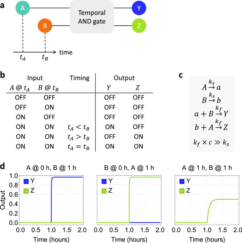
Figure 1.
Concept and chemical reaction network implementation of temporal logic circuits. (a) Abstract circuit diagram, (b) truth table, (c) chemical reaction network implementation, and (d) simulations of a two-input temporal AND gate. c is the concentration of input signals A and B. Simulations of output signals Y and Z are shown as relative concentrations to c over time, where c = 100 nM, ks = 0.002/s, and kf = 2 × 10⁶ /M/s.

