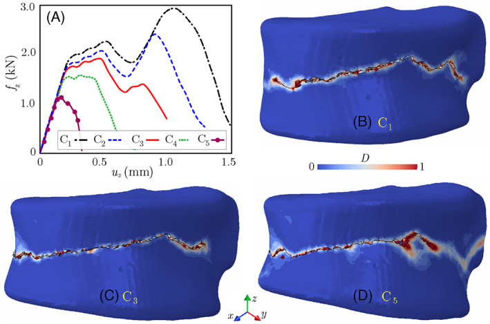
FIGURE 13.

(A) Force‐displacement responses of the lytic vertebra subject to uniform compression and flexion loads; (B–D) damage patterns after failure under loadings C1, C3, and C5. Note that u z is the applied displacement boundary condition in the z direction, while f z refers to the resultant reaction force along the top (or bottom) surface of the vertebra
