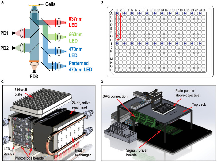
Figure 1.
Swarm instrument schematics. (A) Each objective module contains four excitation LED paths (637, 563, 470 nm, and patterned 470 nm) and three emission channels (736, 573, and 520 nm), which are collected by photodiode detectors. Chrome masks are placed on conjugate image planes to enable patterned blue light stimulation. Beam shaping optics are not shown. (B) 384-well plate and objective modules illuminating 24 wells (blue dots) and scan pattern (red arrow) to image the entire plate. (C) Each individual objective module has two banks of 12 modules that comprise the whole 24-objective read head. Each module contains multiple lenses, filters, and masks to deliver light from the LED board to the bottom of the well. The signal amplification picoammeters measure currents from the sample which are collected by each photodiode channel. Water cooled heat exchangers are fastened to the LED boards. (D) Surrounding superstructure of Swarm. A plate pusher arm articulates a 384-well plate over a 24-objective read head, which is fastened below the top deck. The DAQ connectors hang to the side of the top deck rails.

