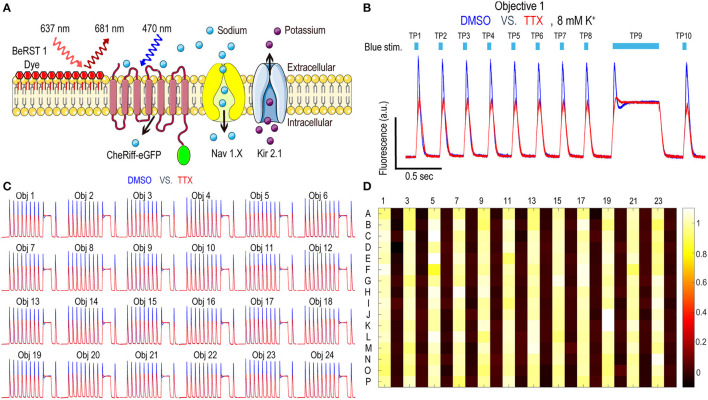
Figure 2.
Nav1.7 Spiking HEK assay performance with the Swarm instrument. (A) Diagram of key components in Nav1.x spiking HEK cells, including voltage sensitive dye BeRST1, CheRiff-eGFP, Kir2.1, and the target of interest, Nav1.x channel. (B) Representative fluorescence traces from eight wells of DMSO or 1 μM TTX treated Nav1.7 spiking HEK cells stimulated with a 10 test-pulse blue light stimulation protocol, imaged by Objective 1 of the Swarm instrument. The bath [K+] is 8 mM. (C) Fluorescence traces collected from all the 24 objectives. The Nav1.7 spiking HEK cells were treated with either DMSO or 1 μM TTX and were stimulated by the protocol shown in (B). Each trace was averaged based on 8 adjacent wells imaged by the same objective. (D) The heat map from a representative Nav1.7 spiking HEK 384-well sentinel plate. All the odd columns were treated with DMSO vehicle control, and all the even columns were treated with 1 μM TTX.

