Abstract
Objectives
To examine anti‐adhesion and anti‐biofilm effects of a diamond‐like carbon coating deposited via a novel technique on the inner surface of a thin silicon tube.
Methods
Diamond‐like carbon coatings were deposited into the lumen of a silicon tube with inner diameters of 2 mm. The surface of the diamond‐like carbon was evaluated using physicochemical methods. We used three clinical isolates including green fluorescent protein‐expressing Pseudomonas aeruginosa, Escherichia coli and Staphylococcus aureus. We employed a continuous flow system for evaluation of both bacterial adhesion and biofilm formation. Bacterial adhesion assays consisted of counting the number of colony‐forming units and visualization of adhered bacterial cells by scanning electron microscope to evaluate the diamond‐like carbon‐coated/uncoated samples. The biofilm structure was analyzed by confocal laser scanning microscopy on days 3, 5, 7 and 14 for green fluorescent protein‐expressing Pseudomonas aeruginosa.
Results
The smooth and carbon‐rich structure of the intraluminal diamond‐like carbon film remained unchanged after the experiments. The numbers of colony‐forming units suggested lower adherence of green fluorescent protein‐expressing Pseudomonas aeruginosa and Escherichia coli in the diamond‐like carbon‐coated samples compared with the uncoated samples. The scanning electron microscope images showed adhered green fluorescent protein‐expressing Pseudomonas aeruginosa cells without formation of microcolonies on the diamond‐like carbon‐coated samples. Finally, biofilm formation on the diamond‐like carbon‐coated samples was lower until at least day 14 compared with the uncoated samples.
Conclusions
Intraluminal diamond‐like carbon coating on a silicone tube has anti‐adhesion and anti‐biofilm effects. This technology can be applied to urinary catheters made from various materials.
Keywords: bacterial adhesion, biofilms, plasma gases, urinary catheters, urinary tract infection
Abbreviations & Acronyms
- 3D
three‐dimensional
- CFU
colony‐forming unit
- CLSM
confocal laser scanning microscopy
- CVD
chemical vapor deposition
- DLC
diamond‐like carbon
- GFP
green fluorescent protein
- OsO4
osmium tetroxide
- SEM
scanning electron microscope
Introduction
Urinary catheters are used worldwide in the field of urology. 1 However, bacteriuria develops in almost 100% of people within 30 days of urinary catheter insertion. 2 Bacteria in the urine adhere to and colonize on the catheter surface, which results in rapid biofilm formation, followed by catheter obstruction and symptomatic urinary tract infection. 3 Various catheters and materials 4 , 5 , 6 , 7 have been developed over the years; however, none have provided completely satisfactory clinical outcomes. Silicone catheters are the most widely used for long‐term indwelling. 1
DLC is an amorphous hard film composed of carbon allotropes. DLC coating, deposited in the Radio Frequency plasma CVD system, was reported to consist of a hydrogenated amorphous carbon type, involving hybrid carbon‐carbon bonds of sp3 and sp2. 8 DLC coatings are considered suitable for application in medical devices because of their biocompatibility along with a number of other useful properties, including low friction, smoothness, abrasion resistance and low cost. 9 , 10 A previous report showed that DLC deposited onto a polyurethane film reduced bacterial adhesion and encrustation. 11 Despite these promising reports, DLC coatings have not been applied for use in urinary catheters, owing to technical limitations associated with application of DLC coatings into the lumen of small‐diameter tubes; DLC coatings were only previously demonstrated on flat surfaces using conventional methods. In 2018, however, Nakatani et al. 12 developed the world’s first technique for DLC coating on the inner surface of a thin tube. As bacterial biofilms are known to develop more in the lumen than on the outer surface of tubular medical devices, 13 coatings exhibiting anti‐adhesion and anti‐biofilm effects should be applied to the lumen. Therefore, the novel technique for DLC coating developed by Nakatani et al. was expected to offer utility for use in urinary catheters.
In the present study, we examined the properties of DLC coating deposited (via a novel technique) on the inner surface of a thin silicon tube. Anti‐adhesion and anti‐biofilm effects, as well as physicochemical and biological properties were evaluated, and compared to those of an uncoated silicon tube.
Methods
DLC coating
A silicon tube with inner and outer diameters of 2 and 3 mm, respectively (LABORAN®; AS ONE Corporation, Osaka, Japan), was used to demonstrate luminal DLC coating. The silicon tube was first washed with ethylene in preparation for coating. The coating process was then performed in the chamber using the AC high‐voltage methane plasma‐enhanced CVD method. 12 The physicochemical properties of the DLC‐coated/uncoated silicon surface were evaluated by 3D non‐contact surface scanning using a New View 5320 (Zygo Corporation, Middlefield, OH, USA) and by scanning electron microscopy using a HITACHI S‐4800 (Hitachi High‐Tech Corporation, Tokyo, Japan). The surface morphology of DLC‐coated/uncoated silicon was visualized with the SEM before and after the bacterial experiments. In addition, the proportions of surface elements on DLC‐coated/uncoated silicon were measured by the energy dispersive X‐ray spectroscopy method using a HITACHI S‐4800, and corrected by the ZAF method.
DLC‐coated/uncoated silicon tubes were cut into 10‐cm samples and used in the experiments assessing both bacterial adhesion and biofilm formation after ethylene oxide gas sterilization.
Bacterial strains and culture conditions
We used three clinical isolates with high capacity for biofilm formation including Pseudomonas aeruginosa OP14‐210, 14 Escherichia coli OE‐128 and Staphylococcus aureus OS‐3, which were isolated from urinary tract infections at Okayama University hospital. pMF230, which is a broad‐host‐range plasmid for constitutive overexpression of GFP was a gift from Dr Michael J. Franklin (Montana State University). 15 To obtain a GFP‐expressing P. aeruginosa strain OP14‐210 (GFP‐expressing P. aeruginosa), this strain was transformed with pMF230 by electroporation. 16
These strains from frozen stocks were grown on trypto‐soya broth (Nissui, Tokyo, Japan) containing 1.5% agar at 37°C. After growth overnight, a single colony from each plate was picked and used as bacterial inoculum in trypto‐soya broth with carbenicillin at 300 μg/mL for GFP‐expressing P. aeruginosa or without antimicrobial agents for E. coli and S. aureus, and grown overnight at 37°C with shaking.
Continuous flow system
The flow system described by Sanchez et al. 17 was modified for evaluation of both bacterial adhesion and biofilm formation. First, the samples were connected to a multichannel pump (IPC8; ISMATEC, Wertheim, Germany) in parallel, and filled with sterile modified artificial urine supplied by the pump from the medium bottle. Then, the inoculum cultures of each bacterial strain grown as described above were injected into the lumen of DLC‐coated/uncoated samples. The samples were clamped and incubated for 2 h to allow the bacterial strains to adhere to the inner surface substratum. After 2 h, sterile modified artificial urine was continuously supplied at a flow rate of 20 mL/h by a pump at 37°C. After 10 min, which was sufficient time to wash away the planktonic bacteria and bacteria that reversibly adhered to the surface, we evaluated the bacteria that adhered irreversibly to the inner surface of the samples using bacterial adhesion assays. For the biofilm formation experiments, sterile modified artificial urine was continuously supplied into the lumen throughout the course of the experiments. 18 The GFP of P. aeruginosa OP14‐210 (pMF230) was expressed in the modified artificial urine, 14 , 18 without carbenicillin, for at least 30 days. The continuous flow system is shown in Figure 1.
Fig. 1.
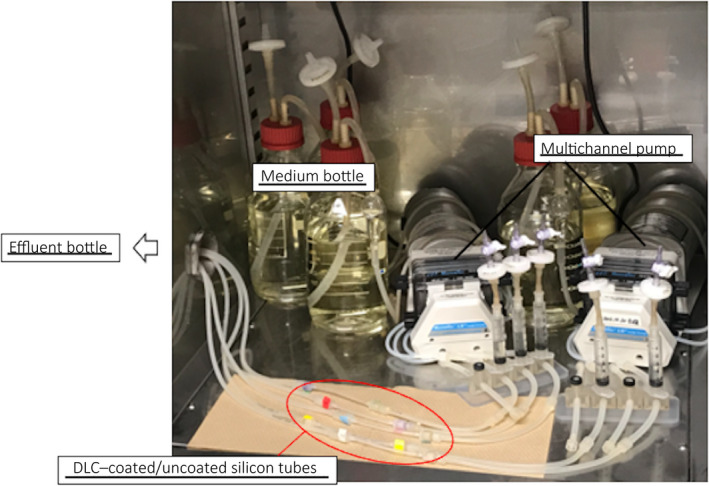
Continuous flow system. This continuous flow system was constructed in the incubator to maintain 37°C.
Bacterial adhesion assays
The bacterial adhesion assays consisted of counting the number of CFUs and visualization of adhered bacterial cells using the SEM in the DLC‐coated/uncoated samples.
For CFU counting, each rinsed sample, cut into fragments of 1 cm, was placed into 1.5‐mL microcentrifuge tubes containing 1 mL sterile saline. The fragments with bacteria were then vigorously vortexed. The suspended bacterial cells were then serially diluted 10‐fold in sterile saline, and 50 μL aliquots of each dilution were spread on Mueller‐Hinton agar plates (Becton Dickinson, Sparks, NV, USA). After overnight incubation at 37°C, CFUs per fragment (mL) were determined using the following formula: CFUs × dilution magnification × 20. We used three strains including GFP‐expressing P. aeruginosa, E. coli and S. aureus for CFU counting, while a total of 15 fragments per strain were evaluated in three independent experiments.
For SEM visualization using a HITACHI S‐4800 device, the samples were fixed with 2% glutaraldehyde and 2% paraformaldehyde in phosphate‐buffered saline overnight at 4°C, postfixed in 1% OsO4, and dehydrated via an ethanol series. The samples were critically dried, cut in half in the sagittal direction, mounted on stubs in the direction where the lumen could be observed, and deposited in OsO4. Stubs were mounted in the SEM to obtain micrographs.
CLSM
To assess biofilm formation, microscopic observations and image acquisitions were performed by CLSM as reported by Sanchez et al. 17 We used a Zeiss LSM 780 (Carl Zeiss Co., Ltd, Oberkochen, Germany) on days 3, 5, 7 and 14 after bacterial inoculation into the samples, which were sufficiently long for the biofilm to mature. 19 3D images and optical z‐sections were generated using LSM ZEN‐software (Carl Zeiss Co., Ltd). Three image stacks were acquired from each sample at 1‐μm intervals in z‐section from the substratum to the top of the biofilm. Three independent experiments were performed according to the same protocol described above. In total, nine image stacks were acquired and analyzed for each DLC‐coated/uncoated sample.
Structural analysis of the biofilm
CLSM images were reconstructed and analyzed quantitatively using the COMSTAT software ver. 2.1. 20 Multiple images obtained at different depths of the biofilm were collected as z‐stacks by 3D reconstruction and consisted of a series of images with 1‐μm intervals in the z‐section. Automatic thresholding and connected volume filtering were used for all image stacks. Quantification of image stacks was based on biomass and average biofilm thickness. The schedule of bacterial experiments including bacterial adhesion assay and biofilm evaluation was demonstrated in Figure 2.
Fig. 2.
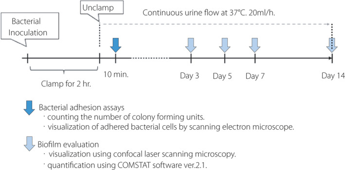
The schedule of bacterial experiments.
Statistical analysis
All data were analyzed using EZR (Saitama Medical Center, Jichi Medical University, Saitama, Japan). 21 Differences in the number of CFUs, biomass and average biofilm thickness between DLC‐coated/uncoated samples were evaluated using a paired t‐test. All P values were two‐sided; a P value < 0.05 was taken to indicate statistical significance.
Results
We observed DLC deposition in the lumen of the silicon tubes in the vacuum chamber (Fig. 3a,b). The DLC‐coated surface showed improvements in smoothness and a high proportion of carbon content (Fig. 4a,b). According to the SEM images, the surface of the uncoated silicone was uniformly rough (Fig. 5a), whereas a film‐like thin structure with fissures could be observed on the surface of the DLC‐coated silicon (Fig. 5b,c). The thin film retained its structure even after long‐term exposure to artificial urine and bacteria for 2 months (Fig. 5d). The coating was also sufficiently flexible that it did not delaminate under external force including bending and friction of the catheter.
Fig. 3.

DLC coating. (a) DLC deposition on the luminal surface in the vacuum chamber. The silicon tube was loaded into the sheath tube. The arrow shows the tip of the silicon tube. Plasma emission throughout the lumen was confirmed, indicating DLC deposition. (b) Pictures of silicon tubes. The DLC coating made the silicon transparent and dark‐yellow in color. A, DLC‐coated silicon tube. B, uncoated silicon tube.
Fig. 4.
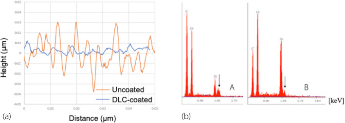
Physicochemical analysis. (a) Roughness (Ra) results measured using a New View 5320. The DLC‐coated surface exhibited a 70% decrease in mean Ra value relative to the uncoated silicon surface. (b) Proportions of elements on the silicon surface. Proportions of surface elements as determined by the EDX method and corrected by the ZAF method using a HITACHI S‐4800. The proportion of carbon increased on the DLC‐coated surface (A) relative to the uncoated surface (B). The arrow indicates the osmium peak. C: carbon, O: oxygen, Si: silicon.
Fig. 5.
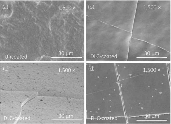
SEM visualization of intraluminal surface structures. All images were acquired at 1500× magnification and accelerating voltage of 5.0 kV. (a) Uncoated silicon surface, vertical direction. (b) DLC‐coated silicon surface, vertical direction. (c) DLC‐coated silicon surface, horizontal direction. Deposition of a DLC layer approximately 3 μm in thickness was confirmed. (d) Surface structure of DLC exposed to artificial urine and bacteria following the experiments, and visualized after removing the adhered cells on the surface with hydrochloric acid.
With regard to the CFU counting, the paired t‐test showed that the mean number of CFUs in the DLC‐coated fragments was significantly lower than in the uncoated fragments for GFP‐expressing P. aeruginosa (9.2 × 10² vs 8.6 × 10³, P < 0.001) and E. coli (9.2 × 10⁵ vs 2.2 × 10⁶, P = 0.036), respectively. In contrast, there was no statistical difference in CFU count between DLC‐coated and uncoated fragments for S. aureus (Fig. 6). Using the SEM, we observed GFP‐expressing P. aeruginosa cells adhered on the inner surface of the DLC‐coated/uncoated samples. GFP‐expressing P. aeruginosa were clustered together and formed some microcolonies with the glycocalyx, connecting cells together on the inner surface of the uncoated samples (Fig. 7a,b). In contrast, GFP‐expressing P. aeruginosa cells were found to spread apart from each other without any extracellular structure on the inner surface of DLC‐coated samples (Fig. 7c,d).
Fig. 6.
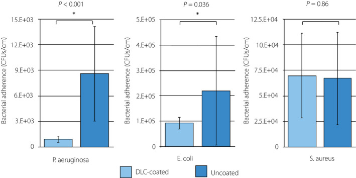
Analysis of CFU counts. The number of CFUs (CFUs/cm) of bacteria irreversibly adhered on the inner surface of the DLC‐coated/uncoated silicon fragments for P. aeruginosa OP14‐210 (pMF230), E. coli OE‐128 and S. aureus OS‐3 were evaluated. Fifteen fragments per strain were evaluated in three independent experiments. P values were obtained using a paired t‐test. Values represent the mean ± SD.
Fig. 7.
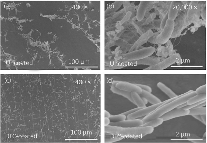
SEM visualization of adhered P. aeruginosa OP14‐210 (pMF230) cells. Visualization of adhered GFP‐expressing P. aeruginosa cells on the inner surface of the samples 2 h after inoculum injection. All images were acquired at accelerating voltage of 5.0 kV. (a) Uncoated, 400×. (b) Uncoated, 20,000×. (c) DLC‐coated, 400×. (d) DLC‐coated, 20,000×.
Visualization by CLSM, as well as 3D analyses, showed that GFP‐expressing P. aeruginosa developed a biofilm on the inner surface of the uncoated silicon sample, with the whole surface covered on day 3 (Fig. 8a‐1). Meanwhile, GFP‐expressing P. aeruginosa developed an uneven biofilm with deficient areas on the inner surface of the DLC‐coated silicon sample (Fig. 8a‐2). In addition, visualization by CLSM, as well as 2.5‐dimensional analyses, showed that the biofilms that developed on the uncoated silicon samples were larger than those on the DLC‐coated samples (Figs 8b‐1,b‐2). Using the COMSTAT program, both biomass and average biofilm thickness were lower for the DLC‐coated samples compared to the uncoated samples on days 3, 5, 7 and 14 (Fig. 8c,d). Based on a paired t‐test, both biomass and average biofilm thickness were lower in the DLC‐coated silicon samples than in the uncoated samples, with statistically significant differences on days 3, 5, 7 and 14. Visualization of the bacteria‐free samples (controls) by CLSM indicated that neither contamination nor biofilm formation could be observed after the conclusion of the experiments.
Fig. 8.
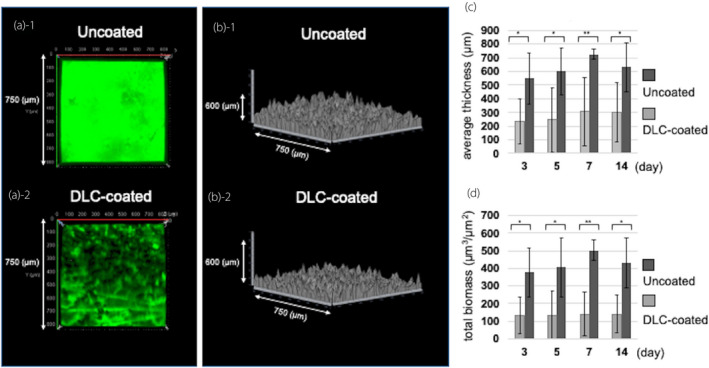
Analysis of biofilm formation by P. aeruginosa OP14‐210 (pMF230). (a, b) Images visualized with a Zeiss LSM780 and reconstructed using LSM ZEN‐software on day 3. All images were taken on a 750 μm × 750 μm square section. (a) Three‐dimensional image. (a‐1) Uncoated. (a‐2) DLC‐coated. (b) 2.5‐dimensional image. (b‐1) Uncoated. (b‐2) DLC‐coated. (c, d) Comparison of the biofilm quantified by reconstructed CLSM images using the COMSTAT software. (c) Average thickness. (d) Total biomass. Values represent the mean ± SD of nine image stacks acquired in three independent experiments. P values were obtained using a paired t‐test. *P < 0.05, **P < 0.001.
Discussion
The results of the present study demonstrate the successful deposition of a DLC coating onto the inner surface of a thin silicon tube. A carbon‐rich and smooth layer was observed following use of a novel DLC‐coating technique, while the structure of the resultant DLC film remained unchanged throughout the course of the experiments. Moreover, the numbers of CFUs suggested less adherence of GFP‐expressing P. aeruginosa and E. coli onto the DLC‐coated silicon fragments compared with the uncoated fragments. SEM images of GFP‐expressing P. aeruginosa cells showed adhered bacteria without formation of microcolonies on the inner surface of the DLC‐coated sample, while CLSM images showed less biofilm formation on the DLC‐coated samples until at least day 14, compared with the uncoated samples.
A clinical study using ureteral stents with a DLC coating only on the outer surface demonstrated that the DLC‐coated stents enabled less painful and easier procedures compared with the stents that the patients had previously experienced, while cystoscopy showed no encrustation and biofilm on the outer wall of the DLC‐coated stent during long‐term indwelling. 22 However, the conventional method of coating deposition on only the outer surface of the stent might not prevent lumen obstruction. DLC‐coated stents would be expected to become even more effective with DLC deposition on both the outer wall and inner luminal surface. Using our novel intraluminal DLC deposition method, we were able to apply the coating to the inner surface of thin urinary catheters made not only of silicon but also of other materials, such as latex rubber.
CFU counting in the present study demonstrated that the DLC coating reduced the numbers of GFP‐expressing P. aeruginosa and E. coli cells irreversibly adhering to the surface. These strains are highly pathogenic in the urinary tract; E. coli is the most common cause of urinary tract infections and P. aeruginosa is the main cause of biofilm formation on urinary catheters. 23 , 24 This result is consistent with previous studies reporting that improved smoothness of the surface structure reduced bacterial adhesion. 11 , 25 , 26 The DLC coating was likely effective at preventing bacterial colonization in the urinary tract, as it was found to strongly reduce adhesion of these gram‐negative bacilli. The DLC coating did not inhibit adhesion for S. aureus. Inconsistency of results among the bacterial strains is probably based on the differentiation of mechanisms in which gram‐positive and gram‐negative bacteria adhere to surfaces; i.e. via matrix molecules in gram‐positive bacteria and via pili in gram‐negative bacteria. 19 , 27 , 28 However, gram‐positive pathogens including S. aureus are a rare cause of catheter‐associated urinary tract infections. 23
P. aeruginosa is one of the most prevalent biofilm‐forming bacteria in the urinary tract. Irreversible adherence of planktonic P. aeruginosa develops within 2 h of initial adhering, and the bacteria subsequently huddle together to form microcolonies. 19 Microcolony formation is an important initial step in biofilm development. The thickness of the P. aeruginosa microcolony then increases, activating quorum‐sensing‐regulated genes, and finally resulting in the development of a mature biofilm within 9–12 days. 19 In the present study, SEM images showed that GFP‐expressing P. aeruginosa adhered to the DLC did not form microcolonies even when the cells were in close proximity to each other. These results could be explained by the possibility that DLC coating prevented the migration and gathering of P. aeruginosa, known as twitching motility. 29 Finally, the DLC coating was found to be effective at inhibiting GFP‐expressing P. aeruginosa biofilm formation until day 14. The results of our physicochemical experiments suggest that the smoothness and non‐corrosiveness of the DLC coating ensured its anti‐biofilm effects in the urine over a prolonged period of time. Furthermore, the high carbon content of the DLC coating may also have contributed to inhibition of biofilm formation, which is supported by the previous report. 30
This study had several limitations. First, the three specific strains selected were validated only using a silicone tube and a modified artificial urine within an intraluminal continuous flow system. The physicochemical properties of the outer surface of the DLC‐coated catheter as well as anti‐adhesion and anti‐biofilm effects were also need to be evaluated using other materials and strains. Second, the mechanism by which DLC inhibited biofilm formation was unclear. Bacterial adhesion assays using GFP‐expressing P. aeruginosa provided a partial explanation for the mechanism of DLC anti‐biofilm effects, but further studies should be conducted. Third, experiments focusing on encrustation, which is just as important as biofilm formation, have not yet been performed. To evaluate the DLC effects with regard to encrustation and the bacteria involved, further studies including in vivo experiments should be performed, preferably over a 14‐day period. However, DLC coating would be expected to greatly reduce the crystalline bacterial biofilm formation according to previous studies. 11 , 22 , 23
The intraluminal DLC coating, deposited on a silicone tube using a novel technique, demonstrated both anti‐adhesion and anti‐biofilm effects. This technology can be applied to urinary catheters constructed from various materials and “fully” DLC‐coated catheters would be expected to exhibit a high degree of utility with less bacterial adherence and subsequent anti‐biofilm effects for prolonged periods of time.
Conflict of interest
None declared.
Author contributions
S. Watari: Protocol development, data collection, data analysis, manuscript writing. K. Wada: Protocol and project development, data management, data analysis, manuscript editing. M. Araki: Project development, data analysis, manuscript editing. T. Sadahira: Data management, manuscript editing. D. Ousaka: Project development, data collection. S. Ozawa: Project development, manuscript editing. T. Nakatani: Project development, data analysis, manuscript editing. Y. Imai: Data collection, data analysis. J. Kato: Data management, manuscript writing. R. Kariyama: Data management, manuscript editing. T. Watanabe: Data analysis, manuscript editing. Y. Nasu: Project development, manuscript editing.
Acknowledgments
We thank Ritsuko Mitsuhata for technical advice and the all other investigators who contributed to this study. We also thank the Central Research Laboratory, Okayama University Medical School for providing the microscope apparatus used in the experiments. This study was funded by a Grant‐in‐Aid for Early Career Scientists (grant number: 19K18585) from the Ministry of Education, Culture, Sports, Science and Technology, Japan.
References
- 1. Venkatesan N, Shroff S, Jayachandran K, Doble M. Polymers as ureteral stents. J. Endourol. 2010; 24: 191–8. [DOI] [PubMed] [Google Scholar]
- 2. Paick SH, Park HK, Oh SJ, Kim HH. Characteristics of bacterial colonization and urinary tract infection after indwelling of double‐J ureteral stent. Urology 2003; 62: 214–7. [DOI] [PubMed] [Google Scholar]
- 3. Vergidis P, Patel R. Novel approaches to the diagnosis, prevention, and treatment of medical device‐associated infections. Infect. Dis. Clin. North Am. 2012; 26: 173–86. [DOI] [PMC free article] [PubMed] [Google Scholar]
- 4. Shepherd AJ, Mackay WG, Hagen S. Washout policies in long‐term indwelling urinary catheterisation in adults. Cochrane Database Syst Rev. 2017; (3):CD004012. [DOI] [PMC free article] [PubMed] [Google Scholar]
- 5. Bonfill X, Rigau D, Esteban‐Fuertes M et al. Efficacy and safety of urinary catheters with silver alloy coating in patients with spinal cord injury: a multicentric pragmatic randomized controlled trial. The ESCALE trial. Spine J. 2017; 17: 1650–7. [DOI] [PubMed] [Google Scholar]
- 6. Dayyoub E, Frant M, Pinnapireddy SR, Liefeith K, Bakowsky U. Antibacterial and anti‐encrustation biodegradable polymer coating for urinary catheter. Int. J. Pharm. 2017; 531: 205–14. [DOI] [PubMed] [Google Scholar]
- 7. Rocca DM, Aiassa V, Zoppi A, Compagnicci JS, Becerra MC. Nanostructured gold coating for prevention of biofilm development in medical devices. J. Endourol. 2020; 34: 345–51. [DOI] [PubMed] [Google Scholar]
- 8. Grill A, Meyerson BS. Development and status of diamondlike carbon. In: Spear KE, Dismuke JP (eds). Synthetic Diamond: Emerging CVD Science and Technology. Wiley, New York, 1994; 91. [Google Scholar]
- 9. Monaghan DP, Laing KC, Logan PA. How to deposit DLC successfully. Mater World. 1993; 1: 347–9. [Google Scholar]
- 10. Bull SJ. Tribology of carbon; DLC, diamond and beyond. Diamond Relat Mater. 1995; 4: 827–36. [Google Scholar]
- 11. Jones DS, Garvin CP, Dowling D, Donnelly K, Gorman SP. Examination of surface properties and in vitro biological performance of amorphous diamond‐like carbon‐coated polyurethane. J. Biomed. Mater. Res. B Appl. Biomater. 2006; 78: 230–6. [DOI] [PubMed] [Google Scholar]
- 12. Nakatani T, Imai Y, Fujii Y, Goyama T, Ozawa S. Novel DLC coating technique on an inner‐wall of extended polytetrafluoroethylene vascular grafts using methane plasma produced by AC HV discharge. J. Photopolym. Sci. Technol. 2018; 31: 373–7. [Google Scholar]
- 13. Wang JC, Tran PL, Hanes R et al. Inhibition of otopathogenic biofilms by organoselenium‐coated tympanostomy tubes. JAMA Otolaryngol. Head Neck Surg. 2013; 139: 1009–16. [DOI] [PubMed] [Google Scholar]
- 14. Kumon H, Ono N, Iida M, Nickel JC. Combination effect of fosfomycin and ofloxacin against Pseudomonas aeruginosa growing in a biofilm. Antimicrob. Agents Chemother. 1995; 39: 1038–44. [DOI] [PMC free article] [PubMed] [Google Scholar]
- 15. Nivens DE, Ohman DE, Williams J, Franklin MJ. Role of alginate and its O acetylation in formation of Pseudomonas aeruginosa microcolonies and biofilms. J. Bacteriol. 2001; 183: 1047–57. [DOI] [PMC free article] [PubMed] [Google Scholar]
- 16. Masduki A, Nakamura J, Ohga T, Umezaki R, Kato J, Ohtake H. Isolation and characterization of chemotaxis mutants and genes of Pseudomonas aeruginosa . J. Bacteriol. 1995; 177: 948–52. [DOI] [PMC free article] [PubMed] [Google Scholar]
- 17. Sanchez Z, Tani A, Suzuki N, Kariyama R, Kumon H, Kimbara K. Assessment of change in biofilm architecture by nutrient concentration using a multichannel microdevice flow system. J. Biosci. Bioeng. 2013; 115: 326–31. [DOI] [PubMed] [Google Scholar]
- 18. Minuth JN, Musher DM, Thorsteinsson SB. Inhibition of the antibacterial activity of gentamicin by urine. J. Infect. Dis. 1976; 133: 14–21. [DOI] [PubMed] [Google Scholar]
- 19. Sauer K, Camper AK, Ehrlich GD, Costerton JW, Davies DG. Pseudomonas aeruginosa displays multiple phenotypes during development as a biofilm. J. Bacteriol. 2002; 184: 1140–54. [DOI] [PMC free article] [PubMed] [Google Scholar]
- 20. Heydorn A, Nielsen AT, Hentzer M et al. Quantification of biofilm structures by the novel computer program COMSTAT. Microbiology 2000; 146: 2395–407. [DOI] [PubMed] [Google Scholar]
- 21. Kanda Y. Investigation of the freely available easy‐to‐use software ‘EZR' for medical statistics. Bone Marrow Transplant. 2013; 48: 452–8. [DOI] [PMC free article] [PubMed] [Google Scholar]
- 22. Laube N, Kleinen L, Bradenahl J, Meissner A. Diamond‐like carbon coatings on ureteral stents–a new strategy for decreasing the formation of crystalline bacterial biofilms? J. Urol. 2007; 177: 1923–7. [DOI] [PubMed] [Google Scholar]
- 23. Flores‐Mireles AL, Walker JN, Caparon M, Hultgren SJ. Urinary tract infections: epidemiology, mechanisms of infection and treatment options. Nat. Rev. Microbiol. 2015; 13: 269–84. [DOI] [PMC free article] [PubMed] [Google Scholar]
- 24. Stickler DJ, Feneley RC. The encrustation and blockage of long‐term indwelling bladder catheters: a way forward in prevention and control. Spinal Cord 2010; 48: 784–90. [DOI] [PubMed] [Google Scholar]
- 25. Hsu LC, Fang J, Borca‐Tasciuc DA, Worobo RW, Moraru CI. Effect of micro‐ and nanoscale topography on the adhesion of bacterial cells to solid surfaces. Appl. Environ. Microbiol. 2013; 79: 2703–12. [DOI] [PMC free article] [PubMed] [Google Scholar]
- 26. Kelten OS, Hepdeniz OK, Tuncer Y, Kankaya DA, Gurdal O. Effect of surface characteristic of different restorative materials containing glass ionomer on Streptococcus mutans biofilm. Niger. J. Clin. Pract. 2020; 23: 957–64. [DOI] [PubMed] [Google Scholar]
- 27. Derek E, Kenneth W. Staphylococcus aureus biofilm: a complex developmental organism. Mol. Microbiol. 2007; 104: 365–76. [DOI] [PMC free article] [PubMed] [Google Scholar]
- 28. Vera C, Brandon W, Henny C, Henk JB. Physico‐chemistry from initial bacterial adhesion to surface‐ programmed biofilm growth. Adv Colloid Interface Sci. 2018; 261: 1–14. [DOI] [PubMed] [Google Scholar]
- 29. O'Toole GA, Kolter R. Flagellar and twitching motility are necessary for Pseudomonas aeruginosa biofilm development. Mol. Microbiol. 1998; 30: 295–304. [DOI] [PubMed] [Google Scholar]
- 30. Sauer K, Cullen MC, Rickard AH, Zeef LAH, Davies DG, Gilbert P. Characterization of nutrient‐induced dispersion in Pseudomonas aeruginosa PAO1 biofilm. J. Bacteriol. 2004; 186: 7312–26. [DOI] [PMC free article] [PubMed] [Google Scholar]


