Abstract
A solution for challenging hip dysplasia surgery could be a patient‐specific 3D‐printed shelf implant that is positioned extra‐articular and restores the dysplastic acetabular rim to normal anatomical dimensions. The anatomical correction and biomechanical stability of this concept were tested in a canine model that, like humans, also suffers from hip dysplasia. Using 3D reconstructed computed tomography images the 3D shelf implant was designed to restore the radiological dysplastic hip parameters to healthy parameters. It was tested ex vivo on three dog cadavers (six hips) with hip dysplasia. Each hip was subjected to a biomechanical subluxation test, first without and then with the 3D shelf implant in place. Subsequently, an implant failure test was performed to test the primary implant fixation. At baseline, the dysplastic hips had an average Norberg angle of 88 ± 3° and acetabular coverage of 47 ± 2% and subluxated at an average of 83 ± 2° of femoral adduction. After adding the patient‐specific shelf implants the dysplastic hips had an average Norberg angle of 122 ± 2° and acetabular coverage of 67 ± 3% and subluxated at an average of 117 ± 2° of femoral adduction. Implant failure after primary implant fixation occurred at an average of 1330 ± 320 Newton. This showed that the patient‐specific shelf implants significantly improved the coverage and stability of dysplastic hips in a canine model with naturally occurring hip dysplasia. The 3D shelf is a promising concept for treating residual hip dysplasia with a straightforward technology‐driven approach; however, the clinical safety needs to be further investigated in an experimental proof‐of‐concept animal study.
Keywords: biomechanics, diagnostic imaging, hip, implant fixation, tissue engineering
1. INTRODUCTION
One of the oldest and most straightforward treatments for hip dysplasia is the shelf arthroplasty. 1 The shelf procedure uses (autograft) bone harvested from the iliac crest placed in an extra‐capsular slot on top of the hip capsule to increase femoral head coverage. 2 In time, the interposed hip capsule is thought to transform into fibrocartilaginous tissue that acts as a load‐bearing surface. 3 , 4 , 5 , 6 , 7 Recent, long term follow‐up studies on the shelf arthroplasty 1 , 2 report similar long‐term results as the periacetabular osteotomy. 8 This might shed new light on the shelf arthroplasty when compared to the highly invasive periacetabular osteotomy, as the latter is associated with a long learning curve, long rehabilitation periods and major complications (6%–37%). 8 However, despite the promising results of the shelf arthroplasty, there are still some limitations to the technique. The traditionally well‐placed shelfs show good superior femoral head coverage on radiographs but deficient coverage in the anterior and posterior quadrants on postoperative CT analysis. 9 Furthermore, graft positioning is critical for the success of the shelf arthroplasty. 9 , 10 When the bone graft is placed too high, it might resorb due to lack of mechanical loading. 10 , 11 , 12 When the bone graft is placed too low or is too large, impingement of the femoral head and neck will occur. 11 , 13 Reasonably, the better the fit and size, the better the long‐term outcome might be, 10 , 14 , 15 and therefore the success of the shelf arthroplasty could be improved by creating a better three dimensional (3D) fit and positioning of the shelf implant.
With the current progress in 3D printing technologies, 16 a personalized 3D‐printed shelf implant could enable a seamless fit to the hip socket and increase femoral coverage in all load‐bearing quadrants. 17 The use of a pre‐planned and 3D printed titanium shelf implant to treat hip dysplasia is novel to the authors' knowledge based on extensive screening of the literature. Therefore, a large animal dog model, based on naturally occurring hip dysplasia, was used to investigate this concept. 18 Dogs frequently have hip dysplasia and undergo diagnosis and treatments procedures similar to humans including pelvic osteotomies, total hip replacements and the shelf arthroplasty. 7 Therefore dogs are considered the animal model of choice for studying hip dysplasia. 18 In dogs the shelf arthroplasty has been previously performed using biocompatible orthopedic polymers (BOP). 19 , 20 During this so‐called BOP procedure, bioresorbable osteo‐inductive fibers were used to create a shelf on the dorsal acetabular rim, this procedure was not pre‐planned in 3D and was therefore entirely dependent on the intraoperative experience of the surgeon. The initial clinical results were promising. However, the fibers induced uncontrolled bone proliferation resulting in poor anatomic remodeling of the dorsal acetabular rim. 19 , 20
This paper presents the anatomical and biomechanical outcomes of a first of its kind pre‐planned and personalized 3D‐printed titanium shelf implant in an ex vivo dog study employing cadaveric dysplastic hips. Moreover, the hypothesis is tested that the 3D shelf implant statistically increases the amount of femoral coverage and dislocation potential at the 12.00 o'clock position by comparing the native acetabulum to the condition after the 3D shelf intervention.
2. METHOD
2.1. Animals
For this biomechanical study the hips of three mongrel dogs (25 ± 2 kg) that were terminated for other non‐orthopedic related experiments were used (Ethical approval nr.2016.II.529.002). Together the three dogs had six ortolani positive dysplastic hips, resulting in six data sets; data are presented as mean ± standard deviation (SD). Hips 1–3 had moderate dysplasia and hips 4–6 had severe dysplasia according to the Fédération Cynologique Internationale (FCI). 21
2.2. Image analysis
The Norberg angle, 21 and the percentage of acetabular coverage were measured on respectively ventrodorsal radiographs and CT scans (Siemens Somatom Definition AS, Siemens Healthcare) with the following standardized parameters: 120 kV, 250 mas, 0.6 mm slice thickness. For the measurement of the acetabular coverage the method of Larson et al. (2015) was used. 22 The CT images were reformatted through all acetabular clockface positions and for each position it was measured, similar to the Norberg angle, how many degrees the femoral head was covered by the dorsal acetabular rim and graphically displayed in a clockface graph. The total acetabular coverage was expressed as the percentage (% = degrees/180° × 100) of the weightbearing part of the femoral head (10:00 to 02:00 o'clock positions) covered by the acetabulum. The whole image analysis process was scripted and took around 5 min per patient.
After image analysis, a simmering maceration process 23 was used on the pelvis and femora, cleaning the skeleton of all soft tissues to better visualize the bony anatomy.
2.3. Implant design
The implants were designed on an anatomical 3D model segmented from the CT images (Figure 1A). The segmentation was done semi‐automatically using standardized bone threshold values (HU 226—upper boundary) on imaging processing software, Mimics Medical 21.0 (Materialise).
Figure 1 .
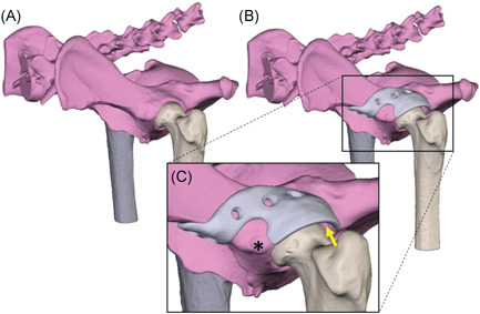
(A) rendering of a canine pelvis with hip dysplasia. (B) Rendering of a 3D‐designed acetabular rim extension implant. (C) Detailed picture of the implant design. The base is designed around the rectus femoris muscle attachment(*). Also it is visible that there is 2 mm space between the implant and femoral head (yellow arrow) to prevent impingement of the hip capsule and act as weight bearing surface [Color figure can be viewed at wileyonlinelibrary.com]
The 3D‐printed acetabular rim implants were designed using Freeform Plus software (Geomagic, 3D Systems) (Figure 1B). The implant's rim extension was designed to increase the acetabular 12.00 o'clock CE‐angle with a minimum of 30° using the diagnostic method of Larson et al. (2015) (Figure 2). 22 The effect of the implant's rim extension in each acetabular clock position was calculated using an in silico range of motion (ROM) simulation in all three degrees of rotational freedom. Subsequently, a board certified veterinary surgeon decided what was the optimal trade‐off between the added acetabular extension and remaining ROM.
Figure 2.
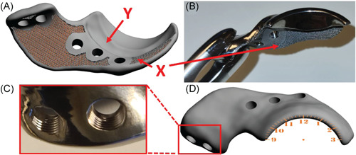
Digital rendering and photos of a 3D shelf implant. (A) Shows a digital rendering of the inside of the implant. Marker ‘X’ shows the porous inner surface of the shelf implant facilitating bone ingrowth for osseous integration and secondary implant fixation and marker ‘Y’ indicates the internal offset of 2 mm on the implant base that to prevent impingement of the acetabular insertion of the hip capsule. (B) Shows a front view of the manufactured implant with the porous scaffold ‘X’ visible. (C) Shows a close‐up of two milled 3.5 mm locking screw holes.(D) Illustrates the external implant surface with a point of view projection of a clockface on the rendered implant [Color figure can be viewed at wileyonlinelibrary.com]
The approved rim extension followed the acetabular curvature with an external offset off 2 mm to allow the hip capsule to be interposed between the implant and the femoral head (Figure 1C). Then, to connect the rim extension to the bone a base was designed with an additional offset along the first 5 mm of the base allowing the insertion of a hip capsule to stay unharmed (Figure 2A). Additionally, the shape of the base was designed in such a way that muscle attachments, for example the rectus femoris cranial to the acetabulum, was spared if a dorsolateral approach to the hip joint was used (Figure 1C).
After the implant's rim and base were determined, the screw holes were planned for primary implant fixation with five 3.5 mm cortical self‐tapping locking screws (DePuy Synthes) (Figure 2C). The screw trajectories were planned in such a way that they did not interfere with the acetabulum but at the same time acquired the maximal possible bone stock for the preferred screw length. The screws were placed bicortical and preferably not parallel to each other. Additionally, the implant–bone interface was made partially porous (70%) to allow bone ingrowth and therefore facilitates permanent (secondary) implant fixation in an in vivo situation (Figure 2A and B). The whole implant design process was scripted and took around 5 min per hip.
2.4. Implant production
The implants were manufactured from medical grade titanium alloy Ti‐6Al‐4V ELI grade 23 by direct metal printing using a ProX DMP320 machine (3D Systems). Postprocessing included chronologically: hot‐isostatic‐pressing, screw wiretapping, polishing, manual cleaning, and autoclave sterilization. The implant production made use of a clinical implant production route (3D Systems) which takes around 14 days per order.
2.5. Biomechanical study
The biomechanical study aimed to determine two parameters: (1) the femoral vector angle (degrees) at which joint subluxation occurred without and with shelf implant, and (2) the implant failure load (N).
2.6. Subluxation potential test
The subluxation potential test was designed in such a way that it mimicked the Barlow 24 and Ortolani 25 tests conducted in veterinary practice. The cranial and caudal ends of each hemi pelvis were embedded in epoxy resin (poly‐pox THV 500, Poly‐Service B.V.) in a neutral position (no angulation). The middle pelvic section surrounding the acetabulum was not embedded to allow the hip joints to move freely during testing and enable fixation of the implant (Figure 3). Furthermore, two holes were drilled in the femur shaft perpendicular to the anatomical axis of the femur. Using two bolts, the femur was attached parallel to the distal end of a hollow aluminum bar. Eight nuts were used to lock the bolts, the femur, and the aluminum bar in place. This aluminum bar was then placed in a custom testing jig designed for use with a universal testing machine (Lloyd instruments LR5K). The testing machine raised the proximal end of the metal bar by raising the pulley (5 mm/min) and simulating a movement from abduction to adduction (Figure 3). To simulate a load bearing situation, a constant force vector of 100 N was generated on the pulley by adding a calibrated weight. The vector angle at subluxation was expressed as the degrees (on the lateral side) between the anatomical axis of the femur in relation to the mediolateral axis of the pelvis which can also be measured using the angle (F in Figure 3) between the aluminum bar (H) and the vertical column of the testing machine. The test started with the pulley in its lowest position, corresponding to a femoral vector angle of 60° (30° of abduction) which points towards the acetabulum and is therefore still a stable position (Figure 3I). By raising the pulley, the femur slowly adducted and the 100 N force vector slowly surpassed the rim of the acetabulum and joint subluxation occurred marked by a sudden drop in resistance, leading to a preprogrammed stop of the testing machine (Figure 3II).
Figure 3.
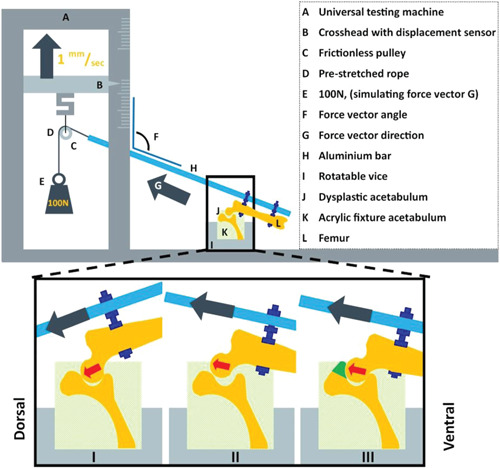
Schematic diagram of the custom‐made set‐up for measuring the dislocation potential of the canine hip joint mimicking the Ortolani test applied in the clinic. I. Dysplastic acetabulum with abducted femur, hip is still centralized because the force vector is directed towards the acetabulum. The test continues by further adducting the femur and increasing the force vector angle (F). II. Dysplastic acetabulum with adducted femur, hip is decentralized (subluxated) because the force vector is directed outwards of the acetabulum. The vector angle at subluxation is measured when the resistance drops. III. Dysplastic acetabulum with implant in situ with adducted femur in same position as in II. Note that the hip remains centralized. The force vector is directed outwards of the acetabulum but the resistance remains intact due to the acetabular rim extending implant (green) indicating that by extending the acetabular coverage the implant adds stability to the hip [Color figure can be viewed at wileyonlinelibrary.com]
Each acetabulum was tested three times and then rotated around the mediolateral axis to five different rotational positions simulating different amount of femoral flexion, resulting in a total of 15 subluxation tests in the native dysplastic hip. The resulting force vectors were aimed at the main weightbearing directions of the acetabulum (10:00, 11:00, 12:00, 01:00, 02:00 clock position) (Figure 2D) as these positions contribute most to joint stability and utilized cartilage surface during normal gait. 26 , 27
After the first round of tests the shelf implants were fixed to the acetabular rim by a board certified veterinary surgeon followed by another CT to evaluate the new acetabular coverage. Thereafter the series of 15 subluxation tests were repeated.
2.7. Break‐out/implant failure test
After the subluxation potential test the biomechanical setup was altered and the specimens were rotated along the longitudinal axis and rigidly fixated using clamp fixtures (Figure 4). The main weightbearing area of the implant (12.00 o'clock position) (Figure 2D) was pressed by the crosshead using a 6 mm diameter indentation attachment (Figure 4A) (Lloyd instruments LR5K). The compression force was generated with a crosshead speed of 1 mm/min until failure occurred. The outcome was the peak force before failure and was defined by a drop in pressure due to breaking or loosening of screws, fracture of the implant, or fracture of the pelvis.
Figure 4.
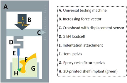
Schematic diagram of the custom‐made testing set‐up for measuring the implant failure force. An isolated stress force is applied on the most dorsal side of the implant (the 12.00 o'clock position) to investigate the peak force (Newton) for implant failure [Color figure can be viewed at wileyonlinelibrary.com]
2.8. Statistical analysis
The hypothesis was tested that the angles of coverage and dislocation at the 12.00 o'clock position were statistically different when comparing the native to the intervention condition, with an alpha level of 0.05 and a power of 80%. Given that a relevant difference was 20°, with a SD of 10° in similar research, 28 , 29 we needed six samples with paired measurements. 30 Statistics were performed in SPSS (v26, IBM) employing a paired student t‐test. Statistics were conducted at the 12:00 o'clock position as this is the main biomechanical focus point for load bearing in the standing position.
3. RESULTS
The acetabular coverage (n = 6) at the 12.00 o'clock position significantly increased from 46 ± 3% in the native hip to 68 ± 2% in the hip with implant, which corresponds to Norberg angles of 88 ± 3° and 122 ± 2°, respectively (Table 1). The total acetabular coverage in the main five weightbearing directions (10:00 to 02:00 clock positions) increased from 47 ± 3% to 65 ± 4% (Figure 5).
Table 1.
Coverage and dislocation angles at the 12.00 clockface position of each native hip and hip with shelf implant. The dislocation angle is the average of three subluxation measurements per hip. Hips 1‐2, 3‐4, and 5‐6 were from the same dogs
| Coverage (°) | Dislocation (°) | |||
|---|---|---|---|---|
| Hip# | Native | Implant | Native | Implant |
| 1 | 89 | 120 | 82 | 113 |
| 2 | 88 | 124 | 81 | 118 |
| 3 | 88 | 122 | 83 | 117 |
| 4 | 90 | 122 | 84 | 119 |
| 5 | 90 | 125 | 82 | 117 |
| 6 | 91 | 124 | 84 | 119 |
| Mean±SD | 88 ± 3 | 122 ± 2 | 83 ± 2 | 117 ± 2 |
| p‐value: | <0.001 | <0.001 | ||
Figure 5.
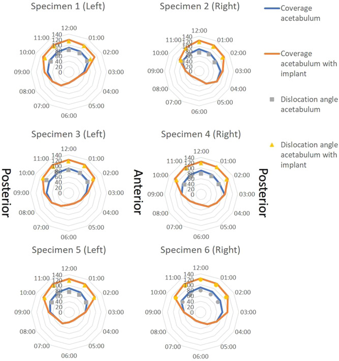
Clock face graphs of each biomechanical hip specimen. Hips 1&2, 3&4, and 5&6 were from the same dogs. The lines provide the Norberg angles calculated on reformatted CT images, so the modified planes align with the clock face positions. The markers show the dislocation angle at which the femur dislocated from the acetabulum in each load‐bearing clock face position with (yellow) or without (grey) shelf implant [Color figure can be viewed at wileyonlinelibrary.com]
The subluxation angle (n = 6) at the 12.00 o'clock position significantly increased from 83 ± 2° in the native hip to 117 ± 2° in the hip with implant (Table 1). The total subluxation potential in the main five weightbearing directions (10:00 to 02:00 clock positions) increased from 77 ± 4° to 110 ± 5° Figure 5).
During the break‐out test the implants failed at 1330 ± 320 N (range: 955–1910 N) at a crosshead translation of 4.7 ± 1.4 mm (range: 2.5–6.3 mm), the equivalent of 283 s. In two cases the first sign of failure was a drop in pressure because of a slipping screw–bone interface at 1125 N and 1406 N at respectively 3.2 mm and 3.8 mm of translation. In four cases the first sign of failure was a drop in pressure because of a pelvic fracture surrounding the implant and screws at 1362 ± 392 N and mean 5.3 ± 0.9 mm crosshead translation (Figure 6).
Figure 6.
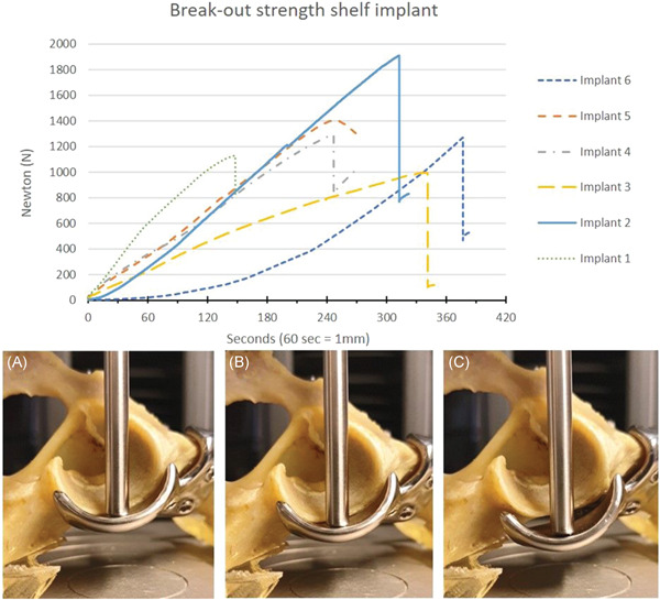
Break‐out strength of the 3D‐printed shelf implant. Hips 1&2, 3&4, and 5&6 were from the same dogs. The graph displays force versus time (displacement) curves in six dog pelvic specimens. All curves show a continued increase of the force until the force suddenly drops by bone‐screw interface failure (#1 and 5) or by pelvic fracture (#2, 3, 4, and 6). The pictures show three consecutive timepoints (90, 180, and 270 s) during testing of specimen #5 (peak force 1405 N at 3.8 mm). At (A) 90 s (1.5 mm, 516 N), the implant is still attached to the bone; at (B) 180 Section (3 mm, 1070 N), the implant is still attached; at (C) 270 s (4.5 mm, 1303 N) there is a distinct reduction in force because of implant detachment by a bone–screw interface failure [Color figure can be viewed at wileyonlinelibrary.com]
4. DISCUSSION
The present ex vivo study provides anatomical and biomechanical outcomes for a personalized 3D‐printed titanium shelf implant to restore normal radiological parameters and stability to the canine dysplastic hip joint. The shelf implant augmented the acetabular rim and significantly improved the femoral head coverage of the dysplastic hip joint. Biomechanical ex vivo testing demonstrated that the stability of the dysplastic hip joint improved significantly post‐implantation. Furthermore, the failure test showed that the primary fixation of the personalized 3D‐printed shelf implants was sufficient to withstand high forces.
The use of pre‐planning to establish shelf size has never been reported to the best of the authors' knowledge. Likewise, the use of 3D printing to create the desired implant for shelf arthroplasty has never been reported. However, there are studies that research the applicability of 3D printed guides to assist peri‐acetabular osteotomies surgery. 31 , 32 Nonetheless, the use of additive manufacturing techniques to create pre‐planned and 3D printed (titanium) implants that restore dysplastic hips to normal radiological values is a first of it's kind use.
In this study the Norberg angle and average acetabular coverage increased to normal values (Norberg > 105). 21 The in silico coverage planning was realized after insertion of the 3D shelf in the cadaveric dysplastic hips. This is an improvement in comparison to conventional free‐hand shelf treatment where optimal shelf position and therefore acetabular coverage is frequently not accomplished. 1 , 8 A high resolution 3D‐printed implant in combination with a patient‐specific anatomical fit makes this procedure a more reliable way of restoring healthy acetabular morphology. By employing subluxation potential test, that was set up to mimic the Ortolani test used in the clinic, it was demonstrated that the femur had to be adducted further to decentralize the femoral head indicating improved joint stability. Within this context, the patient‐specific 3D shelf implant may prevent subluxations, reduce peak forces on the acetabular rim cartilage preventing cartilage micro fissures, and therefore reduce the risk of secondary osteoarthrosis. 33 , 34 , 35
The implant failure force of 1330 ± 320 Newton corresponds to approximately four times body weight (25 kg) of the tested canine cadavers. This easily exceeds the functional forces (1–2 times body weight) applied to the canine hip joint in daily life. 25 , 26 In all specimens, the bone or bone–screw interface eventually failed which was expected since the ultimate strength of titanium is much higher than that of cortical bone. 26 When using these implants in dogs suffering from hip dysplasia, this primary fixation strength is important, as dogs are difficult to restrict in their direct postoperative weightbearing behavior.
There are several limitations inherent to the cadaveric nature of this study. First, the small number of specimens tested might have affected the large range in implant failure between the different hips studied in distance and time (x‐axis) and in the force needed (y‐axis) needed to reach implant failure. However, this variability could also relate to the patient‐specific nature of the implant and unique screw directions. The screw trajectories are unique for each implant and therefore the bone–screw interface could have had more grip in one arrangement than the other. Within the context of safety, optimal arrangements of the screw corridors maximizing implant fixation remain to be determined. Furthermore, the change over time to soft tissues and dysplastic hip capsule, for example hypertrophy and metaplasia are considered to significantly contribute to tightening of the capsule and therefore reducing joint laxity after extension of the acetabular rim. However, this change to the soft tissue could not be studied due to the ex vivo nature of this study and therefore these tissues were removed to allow focus on the bony geometry and initial subluxation potential.
From a clinical perspective, caution is needed in translating the current results to human dysplastic hips. Although there are many similarities between the ball and socket hip joint anatomy in dogs and humans, there are marked functional differences with respect to loading. For example, the front/hind limb weight ratio logically differs between quadruped animals and biped humans. 25 However, the hip dysplasia morphology, diagnostics, and treatment options in both species are so similar that this study provides useful information for designs for human application. 18 Moreover, the high incidence of hip dysplasia in dogs may allow for future clinical veterinary studies exploring further the long term safety and efficacy of the 3D shelf implant.
5. CONCLUSION
This study provides anatomical and biomechanical outcomes for using the 3D‐printed shelf in canine dysplastic hip joints to restore coverage and stability. For a next step, an in vivo experimental study is needed to evaluate the safety of the proof of concept of this surgical implantation and to streamline its introduction to the veterinary clinic and eventually the translation to the human clinic.
AUTHOR CONTRIBUTIONS
BW, Björn Meij, Ralph Sakkers, Harrie Weinans, Koen Willemsen: Conceptualized the study; Koen Willemsen, Marianna Tryfonidou, Björn Meij: Conducted the experiments; Koen Willemsen, Marianna Tryfonidou, Björn Meij, Amir A. Zadpoor: Collected the data; Koen Willemsen, Marianna Tryfonidou, Björn Meij: Analysed the data; René M. Castelein, Peter Seevinck, Harrie Weinans, BW: Supervised the project; Koen Willemsen, Marianna Tryfonidou, Ralph Sakkers, René M. Castelein, Peter Seevinck, Harrie Weinans, Björn Meij, BW, Amir A. Zadpoor: Wrote, edited and reviewed the paper. All authors have read and approved the final submitted manuscript.
ACKNOWLEDGMENTS
The research leading to these results has received partial funding from: the PRosPERoS (PRinting PERsonalized orthopaedic implantS) Project, funded by the Interreg VA Flanders—The Netherlands program, CCI grant no. 2014TC16RFCB046; the Smart industry project 15479 funded through governmental grant by NWO domain TTW and The Dutch Arthritis Society (LLP‐12 and LLP‐22). The funding sources played no role in the study design, data analysis and interpretation, nor drafting of the manuscript or the decision to submit it for publication. Special thanks to the Hogeschool Utrecht for using their biomechanical set‐up.
Willemsen K, Tryfonidou M, Sakkers R, et al. Patient‐specific 3D‐printed shelf implant for the treatment of hip dysplasia: anatomical and biomechanical outcomes in a canine model. J Orthop Res. 2022;40:1154‐1162. 10.1002/jor.25133
REFERENCES
- 1. Willemsen K, Doelman CJ, Sam ASY, et al. Long‐term outcomes of the hip shelf arthroplasty in adolescents and adults with residual hip dysplasia: a systematic review. Acta Orthop. 2020;91(4):383‐389. [DOI] [PMC free article] [PubMed] [Google Scholar]
- 2. Terjesen T. Residual hip dysplasia: is there a place for hip shelf operation? J Child Orthop. 2018;12(4):358‐363. [DOI] [PMC free article] [PubMed] [Google Scholar]
- 3. Smith JT, Goodman SB, Fornasier VL. The histology of a failed shelf procedure. Orthop Rev. 1989;18(10):1069‐1072. [PubMed] [Google Scholar]
- 4. Moll FK. Capsular change following Chiari innominate osteotomy. J Pediatr Orthop. 1982;2(5):573‐576. [DOI] [PubMed] [Google Scholar]
- 5. Hiranuma S, Higuchi F, Inoue A, Miyazaki M. Changes in the interposed capsule after Chiari osteotomy: an experimental study on rabbits with acetabular dysplasia. J. Bone Jt. Surg. ‐ Ser. B. 1992;74(3):463‐467. [DOI] [PubMed] [Google Scholar]
- 6. Diab M, Clark JM, Weis MA, Eyre DR. Acetabular augmentation at six‐ to 30‐year follow‐up: a biochemical and histological analysis. J. Bone Jt. Surg. ‐ Ser. B. 2005;87(1):32‐35. [PubMed] [Google Scholar]
- 7. Böhler N, Chiari K, Grundschober F, Niebauer G, Plenk H Jr. Guidelines for Chiari's osteotomy in the immature skeleton developed from a canine model. Clin. Orthop. Relat. Res. NO. 1985;192(192):299‐311. [PubMed] [Google Scholar]
- 8. Clohisy JC, Schutz AL, St John L, Schoenecker PL, Wright RW. Periacetabular osteotomy: a systematic literature review. Clin Orthop Relat Res. 2009;467(8):2041‐2052. [DOI] [PMC free article] [PubMed] [Google Scholar]
- 9. Klaue K, Sherman M, Perren SM, Wallin A, Looser C, Ganz R. Extra‐articular augmentation for residual hip dysplasia Radiological assessment after Chiari osteotomies and shelf procedures. J. Bone Jt. Surg.—Ser. B. 1993;75(5):750‐754. [DOI] [PubMed] [Google Scholar]
- 10. Nishimatsu H, Iida H, Kawanabe K, Tamura J, Nakamura T. The modified Spitzy shelf operation for patients with dysplasia of the hip. J. Bone Jt. Surg.—Ser. B. 2002;84(5):647‐652. [DOI] [PubMed] [Google Scholar]
- 11. Summers BN, Turner A, Wynn‐Jones CH. The shelf operation in the management of late presentation of congenital hip dysplasia. J. Bone Jt. Surg. ‐ Ser. B. 1988;70(1):63‐68. [DOI] [PubMed] [Google Scholar]
- 12. Wolff J. The law of bone remodelling. Springer Science & Business Media; 2012. [Google Scholar]
- 13. Pauwels F. Biomechanics of the Normal and Diseased Hip. Biomech. Norm. Dis. Hip. 1976. [Google Scholar]
- 14. Tanaka H, Chiba D, Mori Y, et al. Long‐term results of a modified Spitzy shelf operation for developmental dysplasia of the hip in adults and adolescents. Eur. J. Orthop. Surg. Traumatol. 2018;28(7):1341‐1347. [DOI] [PubMed] [Google Scholar]
- 15. Bickel WH, Breivis JS. Shelf operation for congenital subluxation and dislocation of the hip. Clin.Orthop. 1975;No. 106:27‐34. [DOI] [PubMed] [Google Scholar]
- 16. Willemsen K, Nizak R, Noordmans HJ, Castelein RM, Weinans H, Kruyt MC. Challenges in the design and regulatory approval of 3D‐printed surgical implants: a two‐case series. Lancet Digit. Heal. 2019;1(4):e163‐e171. [DOI] [PubMed] [Google Scholar]
- 17. Widmer KH, Zurfluh B. Compliant positioning of total hip components for optimal range of motion. J Orthop Res. 2004;22(4):815‐821. [DOI] [PubMed] [Google Scholar]
- 18. Pascual‐Garrido C, Guilak F, Rai MF, et al. Canine hip dysplasia: a natural animal model for human developmental dysplasia of the hip. J Orthop Res. 2018;36(7):1807‐1817. [DOI] [PubMed] [Google Scholar]
- 19. Jensen DJ, Sertl GO. Sertl shelf arthroplasty (BOP procedure) in the treatment of canine hip dysplasia. Vet Clin North Am Small Anim Pract. 1992;22(3):683‐701. [DOI] [PubMed] [Google Scholar]
- 20. Oakes MG, Lewis DD, Elkins AD, Hosgood G, Dial SM, Oliver J. Evaluation of shelf arthroplasty as a treatment for hip dysplasia in dogs. J Am Vet Med Assoc. 1996;208(11):1838‐1845. [PubMed] [Google Scholar]
- 21. Flückiger M. Scoring radiographs for canine hip dysplasia—the big three organizations in the world. Eur J Companion Anim Pr. 2007;17(Table):135‐140. [Google Scholar]
- 22. Larson CM, Moreau‐Gaudry A, Kelly BT, et al. Are normal hips being labeled as pathologic? A CT‐based method for defining normal acetabular coverage. Clin Orthop Relat Res. 2015;473(4):1247‐1254. [DOI] [PMC free article] [PubMed] [Google Scholar]
- 23. King C, Birch W. Assessment of maceration techniques used to remove soft tissue from bone in cut mark analysis. J Forensic Sci. 2015;60(1):124‐135. [DOI] [PubMed] [Google Scholar]
- 24. Freiberg JA. Early diagnosis and treatment of congenital dislocation of the hip. J Am Med Assoc. 1934;102(2):89‐93. [Google Scholar]
- 25. Chalman JA, Butler HC. Coxofemoral joint laxity and the Ortolani sign. J Am Anim Hosp Assoc. 1985;21(5):671‐676. [Google Scholar]
- 26. Minihane KP, Turner TM, Urban RM, Williams JM, Thonar EJM, Sumner DR. Effect of hip hemiarthroplasty on articular cartilage and bone in a canine model. Clin Orthop Relat Res. 2005;437(437):157‐163. [DOI] [PubMed] [Google Scholar]
- 27. Farese JP, Todhunter RJ, Lust G, Williams AJ, Dykes NL. Dorsolateral subluxation of hip joints in dogs measured in a weight‐bearing position with radiography and computed tomography. Vet Surg. 1998;27(5):393‐405. [DOI] [PubMed] [Google Scholar]
- 28. Comhaire FH, Schoonjans FA. Canine hip dyslasia: the significance of the Norberg angle for healthy breeding. J Small Anim Pract. 2011;52(10):536‐542. [DOI] [PubMed] [Google Scholar]
- 29. Tomlinson JL, Cook JL. Effects of degree of acetabular rotation after triple pelvic osteotomy on the position of the femoral head in relationship to the acetabulum. Vet Surg. 2002;31(4):398‐403. [DOI] [PubMed] [Google Scholar]
- 30. Sanjeev B. Fundamentals of Biostatistics. 4th ed. Nelson Education; 2006:221. [Google Scholar]
- 31. Zhou Y, Kang X, Li C, et al. Application of a 3‐dimensional printed navigation template in Bernese periacetabular osteotomies: a cadaveric study. Medicine (Baltimore). 2016;95(50). [DOI] [PMC free article] [PubMed] [Google Scholar]
- 32. Otsuki B, Takemoto M, Kawanabe K, et al. Developing a novel custom cutting guide for curved peri‐acetabular osteotomy. Int Orthop. 2013;37(6):1033‐1038. [DOI] [PMC free article] [PubMed] [Google Scholar]
- 33. Kotlarsky P, Haber R, Bialik V, Eidelman M. Developmental dysplasia of the hip: what has changed in the last 20 years? World J Orthop. 2015;6(11):886‐901. [DOI] [PMC free article] [PubMed] [Google Scholar]
- 34. Olmstead ML. Small animal orthopedics. 365–368. Mosby; 1995:368. [Google Scholar]
- 35. Vanden Berg‐Foels WS, Todhunter RJ, Schwager SJ, Reeves AP. Effect of early postnatal body weight on femoral head ossification onset and hip osteoarthritis in a canine model of developmental dysplasia of the hip. Pediatr Res. 2006;60(5):549‐554. [DOI] [PubMed] [Google Scholar]


