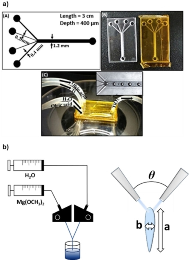
Figure 11.

a) Schematic design and digital pictures of the chip reactor employed in Ref. [56]. Reproduced with permission from Ref. [56], Copyright IOP Publishing, 2018. b) Schematic of the system containing the IJM (left) and representation of the mixing zone.
