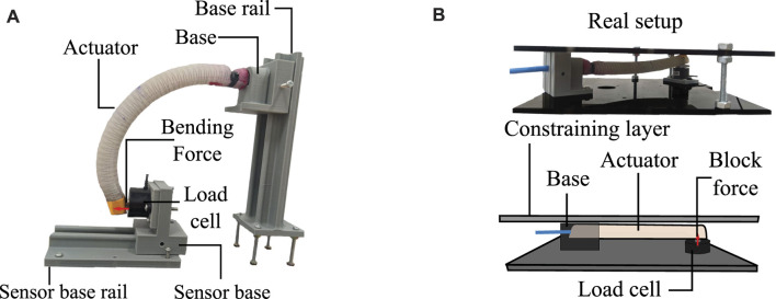
FIGURE 5.
Test of force exerted by the actuators. (A) Configuration for bending force measurement. It can be seen how the clamping system of the sensor and the actuator can modify its location through rails to adjust the tip of the actuator with the load cell. (B) Configuration for blocked force measurement. The upper image shows an actual image of the test. The lower image shows a graphical explanation showing the key elements of the setup.

