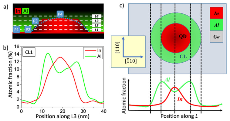
Figure 7.
(a) Scheme of a QD capped by an AlAs layer. L1 to L4 are directions parallel to the growth plane where the compositional profiles are taken. P1 to P4 are the positions for punctual measurements. (b) Experimental compositional profiles along the line L3 for a QD in the CL1 layer. (c) Plan view of a slide of the QD capped with AlAs and its correspondence with the theoretical composition profiles for In and Al.

