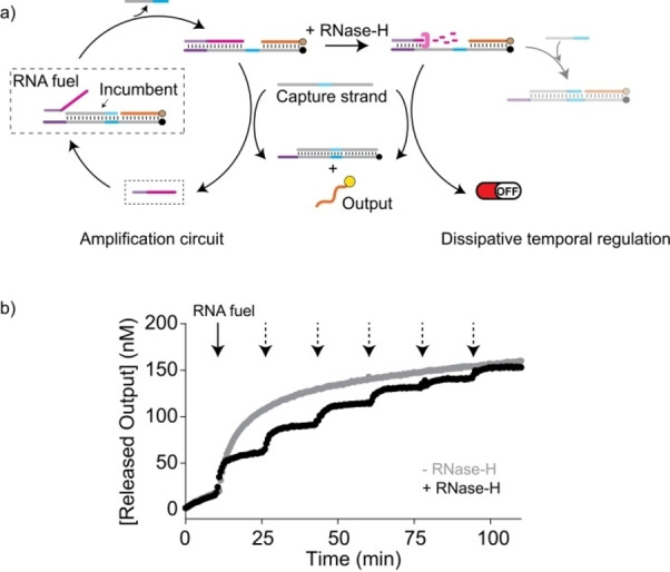
Figure 6.

a) Temporal control of a self‐amplification circuit using dissipative strand displacement. A separate output and an additional capture strand drive a self‐amplification reaction upon fuel strand addition (left). Under dissipative conditions, the fuel is degraded and the self‐amplification is stopped (right). b) Time trajectory of the output strand release upon addition of RNA fuel strand (50 nM, indicated by black arrows) in the absence (grey curve) or presence (black curve) of RNase H (15 U mL−1). Due to the transient amplification in presence of RNase H, the amplification could be initiated multiple times by repeated addition of RNA (indicated by dashed arrows). The amplification system in the solution contained 300 nM of target, incumbent, output and capture strands.
