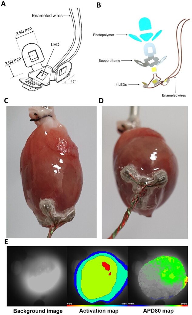
Figure 4.

Overview of the apex cup device. (A) Schematic drawing and (B) exploded schematic view of the LED assembly. The centrally localized LED chip at the base of the assembly can be activated independently of the other three LEDs. (C and D) Images of the LED device mounted to the apex of a Langendorff-perfused TAC heart. Firm fixation of the LED device was ensured with tissue adhesive. (E) Typical activation (middle panel) and action potential duration at 80% repolarization (APD80, right panel) maps of the apex during sinus rhythm of a ReaChR-expressing TAC heart after it was subjected to repeated LED device activation during in vivo and ex vivo experiments with all LEDs activated for both 567 nm light (15 mW/mm2) and 617 nm light (10 mW/mm2). Recordings were made following LED device removal and with the camera pointed at the tip of the apex (left panel). The activation map demonstrated rapid and regular activation of the epicardial apical surface. The decrease in isochronal line spacing at the edges is due to the curvature of the apex. The APD80 map demonstrates a homogenous APD of 60–70 ms.
