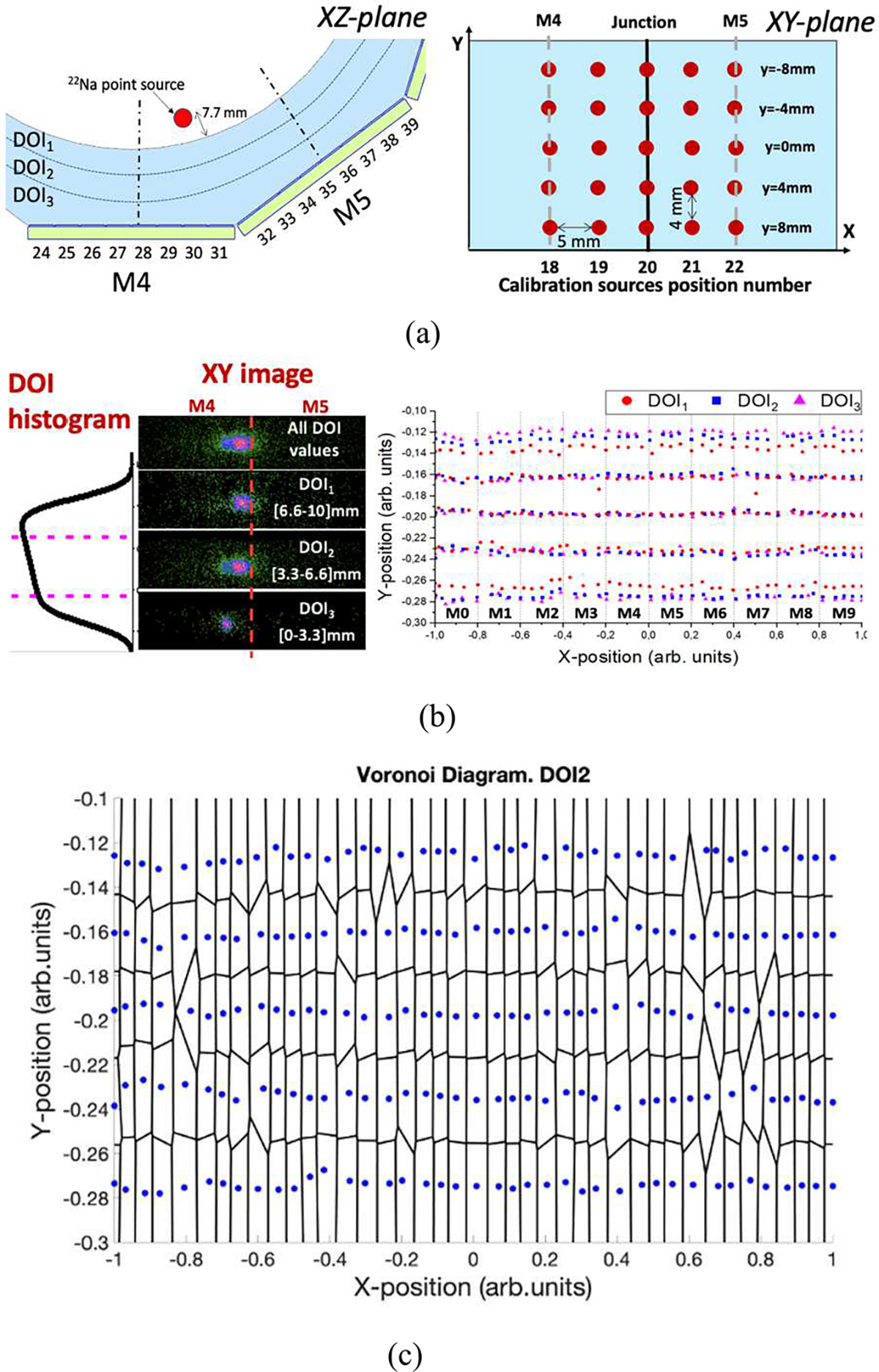
Fig. 3.

(a) Schematic of a calibration source close to the junction between two facets on XZ-plane and schematic of different calibration source positions on XY-plane, (b) Flood maps (x and y coordinates) of the source number 20 at y=0 mm; including, from top to bottom, all DOI values, DOI1 (impact at the entrance of the scintillator), DOI2 and DOI3 (impacts closer to the photosensor) and measured impact position as a function of the DOI layer for the 200 calibration positions; and (c) Voronoi Diagram of the measured source positions for DOI2 layer.
