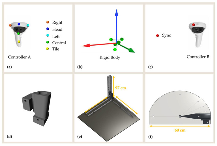
Figure 2.
(a) Controller A and markers configuration used to define the (b) rigid body. (c) Controller B and position of the synchronization marker. Controller A was allocated in a (d) custom-made support designed to be easily moved on the structures for (e) translational and (f) rotational movements.

