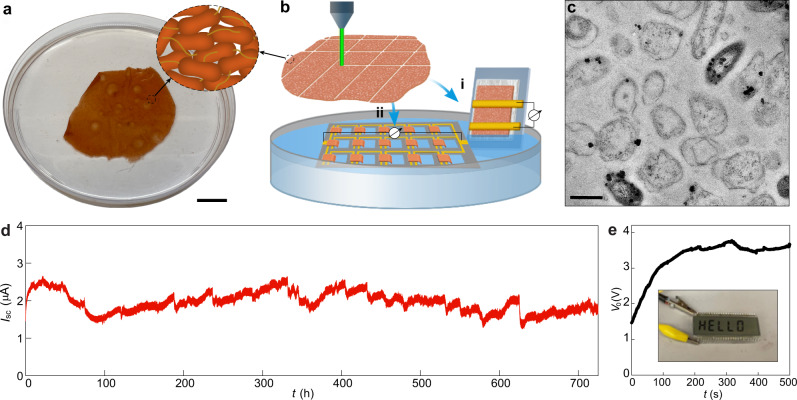
Fig. 1. Electric outputs from G. sulfurreducens biofilms.
a A harvested biofilm sheet of G. sulfurreducens strain CL-1 (schematic inset), floating on water. Scale bar, 2 cm. b Schematic of using laser-patterned biofilms to construct (i) single device and (ii) interconnected device array on a PDMS substrate (gray), with a portion of the biofilm at one electrode immersed in water. A tissue paper was used to support the biofilm in the single device, which may assist water evaporation but does not contribute to electric signals (supplementary Fig. S4). c Cross-sectional TEM of a G. sulfurreducens strain CL-1 biofilm. Scale bar, 1 µm. d A continuous recording of the short-circuit current (Isc) from a device for one month. The device had the structure shown in (b-i), with an electrode spacing 2 mm and lateral width 1 cm, yielding an estimated energy density Vo·Isc/4 of ~1 µW/cm2 in the active biofilm region. The test was performed in the ambient environment with relative humidity (RH) fluctuating between 30–55%. e Open-circuit voltage (Vo) from an integrated device array (bii) floating on a water surface, which was used to power up an LCD (inset). The actual device is shown in supplementary Fig. S8.

