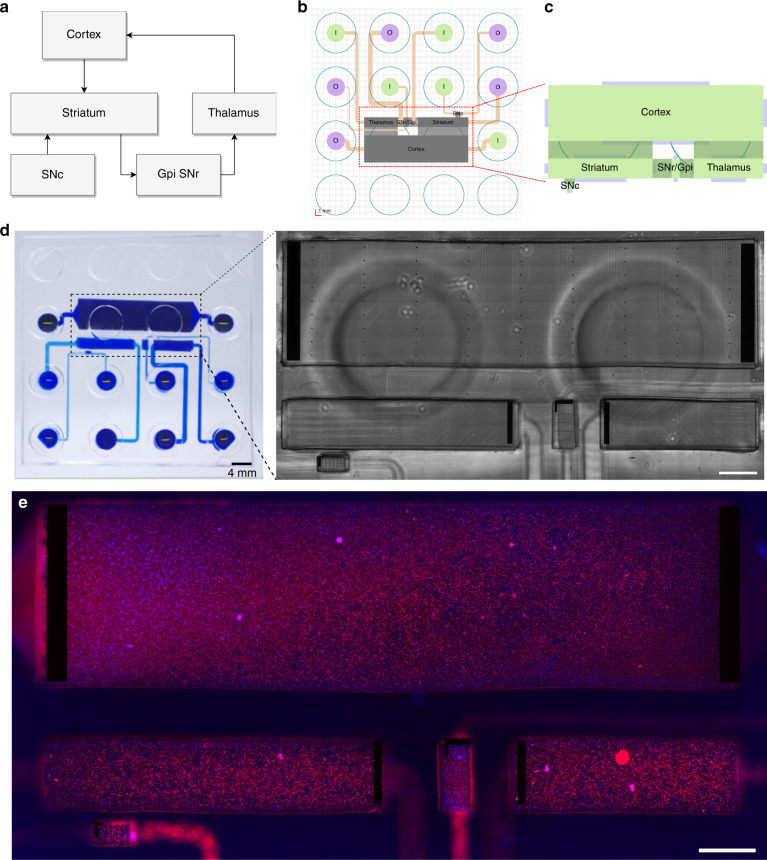
Fig. 6. Implementation of the neurofluidic framework for the construction of the basal ganglia circuit on a chip.
a Scheme representing the regions and connections within the in vivo circuit. GPi: Glubulus Pallidus internal, SNr: Substantia Nigra reticularis SNc: Substantia Nigra compacta. b Structural setting and positioning of the inlet and outlet channels, together with their respective input and output reservoirs. c Schematic representation of the in vitro application of the deposition chambers. d Image of the reconstructed basal ganglia circuit on a chip using the deposition chamber technology, where all compartments are filled with blue ink. Inset: Transmission light microscope image of the multi-electrode array aligned on the neurofluidic architecture. The image was obtained using a x10 objective. e Immunofluorescent pictures of 18 DIV embryonic rat hippocampal with anti-MAP2 (Red) and with DAPI (blue). All images were obtained using a x10 objective. Scale bars represent 1 mm

