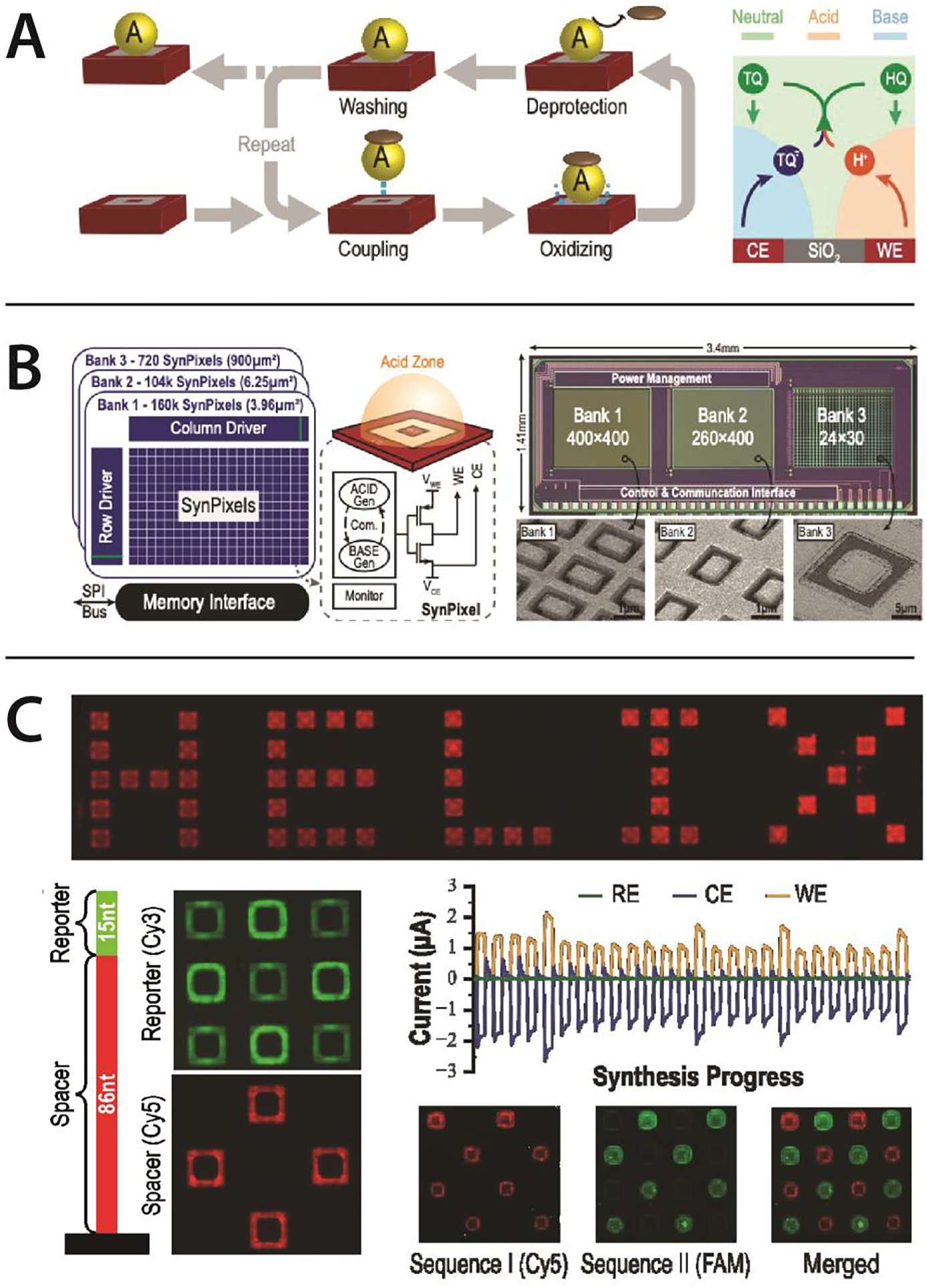
Figure 4. DNA synthesis by electrochemistry.

(A) (Left) Cycle of synthesis, illustrated adding a phosphoramidite to a site: deprotection is driven by localized acid generation at the site. (Right) Localized Acid for deprotection, achieved by decomposition of Hydroquinone (HQ) to release H+ acid at the local Working Electrode (WE), and active removal of acid by recombination with a cognate base, oxidized tetrachloro-1,4-benzoquinone (TQ) generated at the local Counter Electrode (CE). (B) DNA synthesis chip. (Left) A CMOS chip device to drive on-chip DNA synthesis. The chip has three sub-arrays of synthesis pixels (SynPixels) of different sizes to illustrate scalability: Banks 1—3 have pixels with footprint (in microns) 2 × 2, 2 × 3 and 30 × 30 respectively. Each array is controlled by row and column driver circuits, which program the pixels for activation, and provide connection to peripheral current monitoring circuits to monitor the electrochemical processes. (Middle) Voltage control of the central Working Electrode (WE) for acid generation and surrounding Counter Electrode (CE) for base generation, is controlled by a transistor switch circuit. (Right) Annotated microscopic image of the CMOS chip die, showing chip size and subarray dimensions. Insets show electron microscope images of the central Platinum WE and common peripheral CE. (C) On-chip scalable 100-mer synthesis. (Upper) Example of localized, controlled synthesis of oligos on the pixel array, spelling out “HELIX”, with synthesis visualized via a fluorescent microscope image of the synthesized oligos labeled by hybridizing to a fluorescently labeled complementary oligo. (Lower Left) Structure of the 100-mer oligo: 86 nucleotide (nt) poly-T and 15 nt complex sequence. Signals from red (Cy5) and green (FAM) labelling oligos hybridized to these segments are shown. Oligo synthesis is seen to be primarily in the annular silicon surface area between the central platinum electrode surrounding platinum counter electrode. (Lower Right) Example of checkerboard pattern synthesis of two different 15 nt sequences, illustrating the ability to sequence independent sequences at each site, along with the current versus time observed during the 30 cycles of synthesis, showing the net electrochemical currents drawn on the array by the Working Electrodes (WE) and Counter Electrodes (CE) (the information and images are through personal communication with Barry Merriman of Avery Digital Data).
