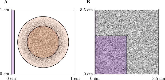
Fig. 7.
Simulation setups for the scar (A) and spiral wave (B) test problems. The orange (pale orange) region depicts the scar region (border zone), which exhibits non-conductive fibrotic elements (black pixels) and decreased conductivity. Purple regions indicate stimulus locations. For the spiral wave setup, self-sustained excitation is initiated by appropriately timed stimuli in the cross field stimulus configuration, as pictured.

