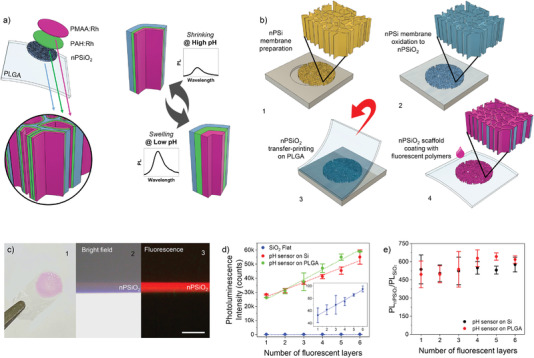
Figure 1.

Preparation of the bioresorbable fluorescence pH sensor. a) Sketch of the pH sensor architecture and operation principle. The sensor consists of a micrometer‐thick nanostructured porous silicon oxide (nPSiO2) membrane coated with a nanometer‐thick pH‐responsive stack of two polymers labelled with Rh fluorophores (PAH:Rh and PMAA:Rh). b) Main fabrication steps of the pH sensor on PLGA substrate: 1) preparation of a ≈5‐µm‐thick nPSi membrane via two‐steps electrochemical silicon etching; 2) thermal oxidation of the nPSi membrane to nPSiO2; 3) transfer‐printing of nPSiO2 membrane onto a ≈40‐µm‐thick PLGA film; 4) layer‐by‐layer conformal coating of the nPSiO2 scaffold with a nanometer‐thick multilayer stack of PAH:Rh and PMAA:Rh. c) 1) Picture of the bioresorbable pH sensor highlighting the Rh‐coated nPSiO2 membrane (pink area) on the PLGA foil; 2) bright‐field and 3) fluorescence optical microscope images of the cross‐section of the nPSiO2 scaffold LbL‐coated with Rh‐labelled polyelectrolytes. Scale bar is 10 µm. d) Photoluminescence intensity at 580 nm versus number of Rh‐labelled polyelectrolyte layers assembled in the nPSiO2 scaffold either transfer‐printed on PLGA foil or left on the native Si chip, as well as on flat SiO2 substrate used as control. The inset highlights the photoluminescence intensity measured on flat SiO2 substrate (n = 3 samples for each polyelectrolyte architecture). e) Ratio of the photoluminescence intensity (at 580 nm) achieved on nPSiO2 scaffolds and flat PSiO2 substrate (i.e., PLnSiO2/PLSiO2) versus number of Rh‐labelled polyelectrolytes of the multilayer stack (n = 3 samples for each polyelectrolyte architecture). All data are presented as mean (± s.d).
