

Summary
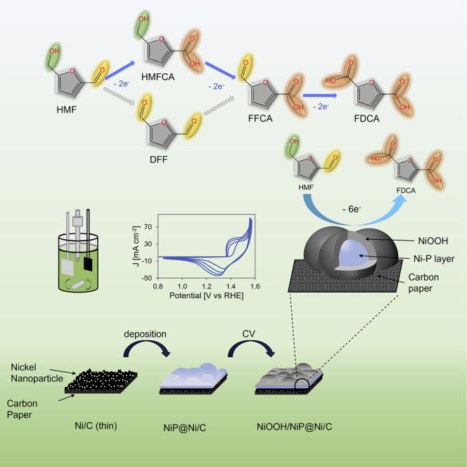
Electrochemical 5-hydroxymethylfurfural oxidation reaction (HMFOR), as a clean biorefinery process, promotes a circular economy with value-added products. In HMFOR, the intrinsic catalytic activity and charge transfer mechanisms are crucial. Herein, nickel, co-deposited with phosphorus (Ni-P), attains superior electrocatalytic performance compared with Ni and its oxyhydroxides for the HMFOR. Such electrocatalytic activity of the Ni-P catalyst is attributed to the high oxidation state of surface Ni species, supported by the bulk Ni-P component. An unprecedented charge storing capacity enabled by the bulk Ni-P material maintains the spontaneous reaction between HMF and Ni3+ species to achieve a current density of 10 mA/cm2 normalized by the electrochemical active surface area at a low potential of 1.42 V vs RHE, reaching a 97% Faradaic efficiency toward 2,5-furandicarboxylic acid. This work, for the first time, sheds light on the importance of the electrode bulk material by showcasing the HMFOR via the Ni-P catalyst incorporating a charge-holding bulk component.
Subject areas: Chemistry, Catalysis, Electrochemistry, Biomass
Graphical abstract
Highlights
-
•
Ni-P catalyst synthesized via cathodic Ni plating on the Ni-deposited carbon substrate
-
•
Ni-P catalyst possesses an excellent oxidation charge storing capacity
-
•
Core of Ni-P catalyst supports spontaneous HMFOR to FDCA at a low potential and OCP
-
•
97% FDCA Faradaic efficiency achieved with stable FDCA production of 10 cycles
Chemistry; Catalysis; Electrochemistry; Biomass
Introduction
As one of the byproducts in the biorefinery industry, 5-hydroxymethylfurfural (HMF) is a biomass-derived furanics chemical that is usually produced from dehydration of hexose sugars (Zhao et al., 2021). It has become a promising bio-based chemical intermediate for its abundant source from biomass such as fructose and its conversion into valuable platform chemicals (Giannakoudakis et al., 2021). The market price of HMF was more than 500 USD/kg, with a market size of 56 million USD in 2019, and the expected compound annual growth rate (CAGR) of the HMF market is 1.45% before 2025 (Kong et al., 2020). Its oxidation product, 2,5-furandicarboxylic acid (FDCA), is considered an important platform chemical and precursor in various industrial syntheses for products including pharmaceutical, agricultural, and polymeric materials (Giannakoudakis et al., 2021; Simoska et al., 2021). The market size of FDCA is expected to be over 780 million USD in 2027, having a CAGR of 8.7% from 390 million USD in 2018 (2,5-Furandicarboxylic Acid (FDCA) Market Size Worth USD 786.3 Million by 2027: Reports and Data, 2021). One of the most desired products from FDCA is polyethylene furanoate (PEF) that possesses similar or superior thermal, mechanical, and barrier properties and is more sustainable than the currently used petroleum-based polyethylene terephthalate (PET) (Eerhart et al., 2012). The prime objective would be to replace the PET plastic bottles with the better PEF that has the potential to quickly reach a large-scale production. Depending on the first oxidation location on the molecule, the oxidation of HMF has two paths, one through the oxidation of the aldehyde group yielding an intermediate called 5-hydroxymethyl-2-furancarboxylic acid (HMFCA), and another through the oxidation of the hydroxyl group via 2,5-diformylfuran (DFF), but both ways lead to the intermediate 5-formyl-2-furancarboxylic acid (FFCA) and the final product FDCA (Scheme 1) (Liao et al., 2020). By valorizing the biomass byproducts such as HMF via clean energy, a circular economy model can be established, which benefits both the biorefinery industry and the general public, rendering the electrochemical oxidation of HMF a highly researched topic. A recent techno-economic analysis demonstrates the considerable merits of electrochemical oxidation of HMF in both energy and material perspectives compared with conventional thermal catalysis (Patel et al., 2022). Another profound benefit of this technique is the potential to reduce CO2 emission owing to the use of clean energy (e.g., renewable electricity) that can transform the conventional fossil-fuel-powered thermal treatment into a more sustainable biorefinery process. In fact, the number of publications regarding this electrocatalytic process has seen an increase since 2010 (Figure S1).
Scheme 1.

HMFOR pathway
HMF oxidation reaction route and intermediates toward FDCA as the final product.
Early works on the oxidation of HMF utilized precious metals such as Au and Pd, via an aerobic oxidation process that often used harsh conditions (high temperature, high O2 pressure, toxic chemical agents, etc.) (Liao et al., 2020). However, single metal catalysts of Au, Pt, and Pd were not particularly selective for the final product FDCA, and the focus was later shifted toward transitional metal catalysts including Ni, Co, Fe, and Cu inspired by the water-splitting process (Deng et al., 2020b; Nam et al., 2018; Song et al., 2021; Zhang et al., 2020). Meanwhile, there have been studies using 2,2,6,6-tetramethylpiperidine 1-oxyl (TEMPO) or its derivative as the mediator and noble metals (Au, Ag, etc.) as the working electrode for homogeneous HMF oxidation (Chadderdon et al., 2019). However, the homogeneous catalysis method still faces feasibility challenges including material and separation costs. Among recent studies, various transition metal-based electrocatalysts were synthesized with p-block elements such as boron, carbon, nitrogen, oxygen, phosphorus, and sulfur (Barwe et al., 2018; Jiang et al., 2016; Kang et al., 2019; Liu et al., 2018; Wang et al., 2021; You et al., 2016a, 2016b; Zhang et al., 2019). Since then, some impressive results have been obtained in electrochemical performance metrics, such as the total current density (>200 mA cm−2 by Ni2P NPA/NF and Ni3S2/NF) (You et al., 2016a, 2016b) and Faradaic efficiency (98–99% by NiFe LDH and Ni3N@C) (Liu et al., 2018; Zhang et al., 2019). Meanwhile, mechanic studies have also shown the active sites to be the transition metal with higher oxidation states including hydroxide, oxyhydroxide, and their coordination species (Deng et al., 2020a, 2021; You et al., 2017). It is understood that for nickel-based catalysts, a higher oxidation state is required for complete HMF oxidation, which should be the main goal for catalyst design and synthesis. However, most of the works have focused on increasing the surface area to achieve a higher current, which can sometimes hinder the analysis of the intrinsic catalytic activity of the material. Therefore, with respect to the catalyst activity toward HMF oxidation reaction (HMFOR), it is also important to compare the current density normalized by the electrochemical active surface area (ECSA) while taking into account the selectivity of the product. In addition to surface modification or surface engineering of the catalyst, the bulk material of the catalyst also deserves attention. Recently, nickel-based core-shell-type catalysts have been synthesized and shown superior performance in oxygen evolution reaction (OER) for water splitting (Masa et al., 2017; Stern et al., 2015; Yu et al., 2016). For the HMFOR, as the oxidation state of Ni is key to the reactivity and selectivity, a catalyst with more Ni content available for oxidation can improve the reaction rate. This leads us to believe the role of bulk composition should also be considered for an advanced catalyst design.
In this work, the Ni-P catalyst is synthesized by cathodic Ni plating on a thin Ni-deposited carbon paper substrate (NiP@Ni/C), and it is found that this catalyst is highly active for the HMFOR toward FDCA formation with an excellent oxidation charge storing capacity at a low applied potential of 1.42 V vs reversible hydrogen electrode (RHE) that is spontaneously reactive with HMF to form the final product FDCA at an open circuit condition. The ECSA-normalized current density is superior to other Ni-based catalysts including thin (1–2 nm) and thick (200 nm) Ni-deposited carbon paper (NiC), surface-oxidized Ni-deposited carbon paper (NiOOH/Ni/C), and surface-oxidized nickel foam (NiOOH/NF). NiP@Ni/C also has the highest Faradaic efficiency compared with the other catalysts, which reaches above 99% at the end of the conversion.
Results and discussion
Catalyst synthesis and characterization
The Ni-P catalyst is synthesized by consecutive cathodic linear sweep voltammetry (LSV) scanning on a thin (<2 nm) nickel-deposited carbon paper substrate (denoted as Ni/C (thin)) in an electroless plating solution. Previous studies have used a similar potentiodynamic deposition method based on the electroless co-deposition of Ni and P (Gao et al., 2017). The Ni/C (thin) is obtained by physical vapor deposition of Ni nanoparticles on the carbon paper substrate. The as-prepared catalyst is denoted as NiP@Ni/C while the catalyst after cyclic voltammetry to oxidative potentials acquires an oxidized surface, becoming NiOOH/NiP@Ni/C (Figure 1A). NiOOH/Ni/C is synthesized by a pulse treatment oxidation on the thick Ni/C substrate with 200-nm Ni deposition thickness. NiOOH/NF is also prepared by pulse oxidation but on nickel foam.
Figure 1.

Catalyst synthesis illustration and SEM characterization
(A–H) Synthesis and illustration of the Ni-P catalyst. The surface-oxidized Ni-P catalyst with energy-dispersive X-ray spectroscopy (EDX) for elemental mapping on the (B) cross-section and (C) top view. Following SEM images showcase (D) a carbon paper with nano-layer nickel as the substrate (Ni/C thin); (E) NiP@Ni/C as-prepared; (F) surface-oxidized NiOOH/NiP@Ni/C; (G) thick nickel layer on the carbon paper (Ni/C); (H) surface-oxidized NiOOH/Ni/C; (I) surface-oxidized nickel foam (NiOOH/NF).
The surface illustrations by scanning electron microscopy (SEM) of Ni/C (thin), NiP@Ni/C, NiOOH/NiP@Ni/C, Ni/C (thick) NiOOH/Ni/C, and NiOOH/NF are shown in Figures 1D–1I at various magnifications. It is clear that the Ni nanoparticles do not cover the carbon paper in Ni/C (thin), and after the deposition of the Ni-P catalyst on top, a new layer of deposited material can be seen on both as-prepared and surface-oxidized catalysts. Specifically, from magnifications at 1–10 microns, the morphology is vastly different for Ni/C (thin) and Ni-P samples. The rough surface in the Ni/C (thin) sample is owing to the carbon paper substrate partially covered by nanometer-scale nickel particles and the larger spherical structures on Ni-P samples are newly deposited Ni-P layers. For Ni/C-thick and the surface-oxidized one, they do not show any noticeable difference in morphology. The cracks on some catalyst surfaces are owing to drying before being taken for imaging. From energy-dispersive X-ray analysis (EDX) on the catalyst surface and cross-section (Figures 1B and 1C), Ni, O, and P are seen in the bulk with uniform distribution, whereas Ni and O are rich on the surface layer after surface oxidation and HMFOR. The surface phosphorus content is decreased after HMFOR, likely being released to the electrolyte, whereas a cross-sectional scan shows that P remains in the deeper layer and the bulk of the catalyst (Figure S2).
As-prepared NiP@Ni/C has a mostly amorphous coating layer of Ni-P as found in Figure 2 by X-ray diffraction (XRD) analysis when excluding the carbon substrate signals. Specifically, by comparing with the Ni foam (PDF 00-004-0850) and carbon paper substrate, the Ni-P catalyst did not show prominent nickel-related crystallinity in the mid 2θ range (Co Kα source) from 40° to 100°. From the entire samples of as-prepared and post-HMFOR Ni-P catalysts, signals in the lower diffraction angel indicate that a portion of the catalyst turned into nickel oxide/hydroxide (PDF 01-089-7111) (Figure S3). The broad peak at 30° is the graphite-2H (PDF 04-020-4354) from the carbon substrate, whereas five other peaks between 40 and 100° are attributed to the substrate. Besides, when comparing as-prepared with post-HMFOR Ni-P catalyst powders, slight differences appear at lower diffraction angles, suggesting the potential formation of some nickel phosphorus oxide in the subsurface layer and the bulk, such as NiP4O11 (PDF 04-011-1683). This reveals that when oxidized in an alkaline solution, the catalyst surface turns to nickel hydroxide and oxide species, whereas nickel phosphorus oxide species remain in the sublayer and the bulk of the catalyst.
Figure 2.

X-ray diffraction analysis
On the carbon paper substrate, Ni foam, and powders from as-prepared NiP@Ni/C and post HMFOR NiP@Ni/C.
High-resolution transmission electron microscopy (HR-TEM) is carried out to inspect the catalyst, and Figures 3A and 3B show that the as-deposited Ni-P is an amorphous coated layer on the carbon paper, which aligns with the XRD results. The same amorphous electrodeposited layer has been obtained by previous studies preparing Ni- or Co- and P-containing catalysts (Du et al., 2019; Lian et al., 2018). High-angle annular dark-field imaging (HAADF), in combination with EDX analysis in Figure 3C, reveals the uniform distribution of Ni, P, and O elements, which agrees with the SEM-EDX result. The post-HMFOR catalyst sample, on the other hand, shows that Ni and O are more abundant on the catalyst surface, whereas some P is depleted from the surface layer with the rest remaining in the bulk (Figure 3F). This supports the SEM analysis and confirms that the active surface component is oxidized Ni species. HR-TEM with EDX also shows that Ni is uniform in the bulk and on the surface (Figure S4).
Figure 3.

High-resolution transmission electron microscopy (HR-TEM)
(A–F) High-resolution transmission electron microscopy (HR-TEM), (C) High-angle annular dark-field imaging (HAADF) and energy-dispersive X-ray spectroscopy (EDX) on the scrapped as-prepared Ni-P catalyst; (D–E) HR-TEM, (F) HAADF and EDX on the scrapped catalyst after HMFOR.
The surface composition is verified by X-ray photoelectron spectroscopy (XPS) survey where Ni 2p, P 2p. and O 1s signals are observed (Figure S5). As shown in deconvoluted high-resolution XPS in Figure 4A, the as-prepared NiP@Ni/C catalyst has a clear Ni 2p3/2 peak at 853.5 eV, corresponding to nickel species in the Ni-P solution, and also a Ni0 2p3/2 peak at 852.1 eV, representing a small amount of pure Ni in the catalyst (Li et al., 2016; Wang et al., 2021). Two other 2p3/2 peaks of Ni2+ in Ni(OH)2 and Ni3+ in NiOOH formed by oxidation are also clearly seen as peaks at 855.7 and 857.2 eV (Wang et al., 2020). The 2p3/2 satellite peak and the 2p1/2 peaks are also identified at higher binding energies. Same peaks are present for surface-oxidized NiOOH/NF, but Ni3+ is not found on nickel foam (Figures S6A and S6B), which verifies Ni3+ being the active site on the Ni-P catalyst similar to NiOOH/NF. Figure 4B shows the P 2P region of the as-prepared Ni-P catalyst where a typical P 2p3/2 signal is located at 130.0 eV, along with a partially oxidized P 2p3/2 located at 133.3 eV (Li et al., 2016; Masa et al., 2016). The Ni region XPS scans for the Ni-P catalyst after CV and HMFOR are compared in Figure 4C, where the Ni 2p3/2 peak becomes negligible and the Ni2+ and Ni3+ 2p3/2 peaks are more prominent, signifying a surface oxidation of nickel species on the catalyst, which verifies the existence of nickel oxyhydroxide and nickel hydroxide on the surface. These results also correspond well to the SEM results mentioned previously. In Figure 4D, the P 2P regions show no obvious signal, meaning that the surface is phosphorus depleted, which indicates that the active sites are oxidized nickel species instead of the doped P species as the surface P has leached into the alkaline electrolyte. This agrees with previous studies that have shown a decrease in P content on the catalyst surface after either OER or HMFOR, where a metal oxide layer is formed (Jiang et al., 2016; Liang et al., 2016; Masa et al., 2016; Stern et al., 2015; Yu et al., 2016).
Figure 4.

High-resolution X-ray photoelectron spectroscopy
(A–D) High-resolution X-ray photoelectron spectroscopy of as prepared NiP@Ni/C on (A) Ni 2p spectra; (B) P 2p spectra; XPS of NiP@Ni/C after HMFOR on (C) Ni 2p spectra; (D) P 2p spectra.
X-ray adsorption spectroscopy (XAS) gives additional information on composition and structure of the catalyst. From X-ray adsorption near edge spectra (XANES) shown in Figure 5A, the pre-edge feature of Ni is barely present before the Ni K edge for both as-prepared and surface-oxidized Ni-P catalysts. This indicates that the change in oxidation states of Ni species in these samples does not largely affect the coordination environment of the central Ni atom. The lower intensity of the NiP@Ni/C at the rising edge is a result of higher symmetry, likely owing to the deposited amorphous nickel phosphorus layer (Seo et al., 2011). The rising edge at around 8,345 eV (E0 from the second derivative) demonstrates that the Ni species near the surface of the Ni-P catalyst is less oxidized than most of the other samples, whereas the surface Ni species in oxidized NiOOH/NiP@Ni/C obtains a higher oxidation state. This wider oxidation window is believed to be a result of the various bonding orientations in the Ni layer that helps to contain an extended average Ni oxidation state at various applied potentials (Taitt et al., 2018). Figure 5A, as a result of Fourier transform extended X-ray absorption fine structure spectra (EXAFS), illustrates the similarity in bonding conditions among Ni catalysts without the presence of phosphorus, where Ni-Ni is the dominant bonding condition, with a first shell Ni-Ni peak at 2.49 Å (Figure S7) (Liu et al., 2020). The as-prepared and the oxidized Ni-P catalysts, on the other hand, reveal shorter bonds in the first and the second shells, but no significant long-range ordering, illustrating an amorphous structure with only short-range ordering within the first two shells of neighboring atoms (Li et al., 1999). As peak fittings shown in Figure 5C, the first peak at 2.06 Å is attributed to the Ni-O bond, and slightly wider peak indicates the existence of different bonding conditions with oxygen atoms in the catalyst (Liu et al., 2020). The peak near 3.11–3.26 Å is an evidence of Ni-Ni/Ni-P bonds (Abba et al., 2014). Figures 5D–5F illustrate the k space, real part of R space and the backward Fourier transform q space of the fitting, showing the Ni-O scattering frequency contributes to the first peak, whereas the Ni-Ni and Ni-P scattering paths contribute to the second peak. Fitting details can be found in Table S2, supplemental information. Figure 5B also displays the shift to a more contracted Ni-O peak in the case of NiOOH/NiP@Ni/C, whereas only the first shell Ni-Ni peak intensity is slightly changed for NF after surface oxidation treatment. This agrees with the XPS result on the increase of Ni oxidation state, and it also reveals the creation of active Ni3+ in the sublayer structure of the Ni-P catalyst after oxidation (Scheme 2), however, only surface modification with limited depth occurs on NiOOH/NF. This feature of the Ni-P catalyst is a result of the activation of amorphous transition metal oxide doped with p-block materials and eventually leads to active catalysis supported by the bulk of the catalyst, similar to what has been observed for the OER (González-Flores et al., 2015).
Figure 5.

X-ray adsorption spectroscopy
(A–F) Normalized XANES spectra at Ni K edge and (B) Fourier-transformed k3-weighted EXAFS spectra in Ni R space on the catalysts; (C) Ni-O, Ni-Ni, and Ni-P combined fitting on the Ni-P catalyst, compared with surface-oxidized NiOOH/NiP@Ni/C; Ni-P catalyst fitting (D) in k space; (E) in R space with real components; and (F) in q space by backward Fourier transform.
Scheme 2.

HMFOR on NiOOH/Ni-P HMF oxidation reaction on surface-oxidized NiP@Ni/C catalys
Ni active site and mechanism
It is known from previous studies that the active site for the HMFOR is the nickel hydroxide-oxyhydroxide complex under applied anodic potential, where the Ni2+ species can be oxidized to Ni3+, allowing the spontaneous reaction between the higher oxidation state nickel and the organic molecule (Song et al., 2020; Taitt et al., 2018; Zhang et al., 2019). A series of electrochemical experiments verify that Ni3+ is the main active site of the plated Ni-P catalyst for the HMFOR. Although Ni3+ is present on the active catalyst surface, the mechanism for charge transfer is different when bulk composition varies. During the forward scan in the cyclic voltammetry (CV) in 1-M KOH electrolyte without HMF, the ECSA-normalized current density increases rapidly after 1.36 V on NiP@Ni/C, which is attributed to the nickel oxidation from Ni2+ to Ni3+ (Figure 6A) (Barwe et al., 2018; Houache et al., 2019). This onset potential is slightly more positive on the Ni foam (1.38 V) and thick Ni/C (1.37V) (Figures 6C and 6E). The much larger Ni oxidation peak on NiP@Ni/C indicates a large amount of charge transferred to and stored not only on the surface but also in the bulk of the catalyst. In the presence of HMF, a forward scan (into more anodic potentials) on all these catalysts shows the same onset potential as the Ni oxidation onset potential without HMF, whereas the rising current density shortly after onset follows the same positive slope as the Ni oxidation peak, meaning that the Ni oxidation takes place before the HMFOR and the latter relies on the former. This verifies that the oxidation reaction of the HMF molecule requires the presence of Ni3+, so it remains insignificant before that Ni3+ becomes dominant on the catalyst surface.
Figure 6.

Cyclic voltammetry at 10 mV s−1
(A–F) NiP@NiC; (B) the difference in current density on forward scan (blue solid line) and backward scan (black dotted line); CV on (C) NiOOH/NF; (D) differences in the current density; CV on (E) NiC; (F) differences in the current density. Dashed lines differentiate between dominant surface conditions and reactions. Differences on both forward and backward scans are the scan with 15-mM HMF subtracted by no HMF in 1-M KOH (ECSA-normalized current, without IR correction).
By subtracting the forward scan of HMF absent CV from the HMF present one on NiP@Ni/C, the positive difference in current density begins to show after 1.45 V while peaking around 1.68 V (Figure 6B). Once the potential becomes more anodic than 1.70 V vs RHE, the OER starts to outperform the HMFOR in this experimental condition. In the same plot, the difference of backward scans (also from HMF scan minus without HMF scan) shows two positive peaks around 1.38 and 1.06 V. The presence of only positive peaks instead of negative ones indicates that there are charge transfer processes other than simple nickel redox of the electrode. The peak at higher applied potentials corresponds to oxidation of HMF on Ni3+, which is at a maximum around 1.38 V and then starts to decline when Ni3+ begins to be reduced on the catalyst surface. Moreover, the distinct peak at a lower potential, which corresponds to nickel reduction, implies the partially reduced nickel in the presence of HMF. This confirms the spontaneous charge transfer from the oxidized nickel species to the electrolyte containing HMF. A similar reaction scheme was proposed by Fleischmann et al. (1971). We recognize this to be the main pathway for the HMFOR on NiP@Ni/C. This indirect charge transfer via the Ni2+ and Ni3+ mediation agrees with previous studies on nickel catalysts for many types of alcohol oxidations (Bender et al., 2020a, 2020b; Fa et al., 2018; van Drunen et al., 2014; Xu et al., 2018). In a recent study that demonstrates the difference between the direct and indirect oxidation processes, it is reported that the direct oxidation, or potential-dependent oxidation, only occurs at a higher applied potential where a proposed hydride transfer is responsible for the organic molecule oxidation (Bender et al., 2020a). The same effect is of a much smaller extent in the case of NiOOH/NF (Figure 6D). The first positive peak is owing to the direct (or potential-dependent) charge transfer on the catalyst surface, happening at higher applied potentials. It is the major charge transfer process. This direct charge transfer process is facilitated with stirring, as the nickel foam substrate has a 3D porous structure that allows the electrolyte to pass through. Without stirring the electrolyte, the NiOOH/NF shows much more limited current, where the dominant reaction can be the indirect charge transfer for the HMFOR (Figure 6C). For thick Ni/C catalyst (Figure 6F), there is only one major peak in the backward scan difference at high potentials, which appears to be smaller than the forward difference peak. This indicates a less kinetically favored direct charge transfer process with Ni3+ on this catalyst surface. Comparing the three CV tests and their differences in forward and backward scans, the potential window for the HMFOR on NiP@Ni/C is the widest. This is owing to the electrochemically active bulk material that enables the catalytically active Ni3+ surface to selectively perform the HMF oxidation at both lower potentials (more negative Ni3+ reduction potential) and higher potentials (less selective for the OER). The broader window also means that once the active component of NiP@Ni/C is oxidized, the HMFOR can occur at a much lower potential (1.25–1.40 V). This understanding opens a new way of HMF conversion in alkaline electrolytes with lower applied potentials, hence reducing the operating costs.
A stepwise reaction scheme for the HMFOR is shown in Scheme 3. The first step involves the nickel species oxidation to NiOOH under an alkaline environment (R1); meanwhile, the HMF molecule from the electrolyte is adsorbed on the catalyst surface (R2) before spontaneous reaction with the Ni3+ species, producing oxidized biomass intermediate and the reduced active site as Ni2+ in Ni(OH)2 (R3) (Bender et al., 2020a). Moreover, it is also possible to have direct oxidation of adsorbed HMF via Ni3+ under higher applied potentials (R4) (Taitt et al., 2018). Although some studies report that Ni2+ could be active for the oxidation of organic molecules (R5), it can be seen in the CV that the extent of such reaction pathway remains insignificant, if any (Taitt et al., 2018). From the three CV results, it is noted that after the oxidation peak of Ni, there is a plateau region where the HMFOR experiences mass transfer limitations (Bender et al., 2020a). Increasing the HMF concentration in 1-M KOH electrolyte yields a higher current density at the plateau region, but the increase in current density before or near the onset of Ni2+ oxidation is minimal (Figure S8). This again proves that the catalysis mainly happens on the Ni3+ active site. In addition, it also reveals that the reaction is initially restricted by Ni oxidation (R1) that provides the necessary active surface for the oxidation of HMF after the onset of Ni2+ oxidation, but later the process is predominantly limited by Ni3+ reaction with HMF (R3) at higher applied potentials before the OER takes place. Bode phase plots from electrochemical impedance spectroscopy (EIS) show the appearance of new peaks at a low frequency between the applied potential of 1.38 and 1.48 V with HMF, signifying that the onset for the direct HMFOR is after 1.38 V where the nickel oxidation state is 3 + for both NiP@Ni/C and NiOOH/NF (Figures S9A and S9C). This agrees with previous studies showing that the oxidation of surface Ni2+ to Ni3+ is quick and the subsequent reaction between Ni3+ and the adsorbed organic component is the rate-determining step (Bender et al., 2020a). When the anode surface is reduced by the spontaneous reaction with HMF molecules, EIS at the open circuit potential or smaller applied potential can show the kinetics of the reaction system as any remaining Ni active site accessible to the electrolyte can still cause the HMFOR and be reduced, so the catalyst partially remains active under a smaller applied potential. From the appearance of Ni oxidation in Bode plots at the open circuit potential (OCP, 1.30 V) on NiP@Ni/C with HMF (Figure S9B), it is deduced that the catalyst is still releasing a positive charge to the electrolyte such that there remains an electron transfer between the solid-liquid boundary. A similar but smaller peak is found with reduced NiOOH/NF at the OCP in HMF (Figure S9D). In the absence of HMF, partially reduced NiP@Ni/C again shows a peak that corresponds to nickel oxidation, whereas there is no obvious peak under the OCP on NiOOH/NF without HMF. For NiP@Ni/C, 1.30 V is still above the Ni3+ reduction peak potential (∼1.10 V), therefore it is evident that the bulk of the electrode remains mostly Ni3+ that is active for spontaneous HMFOR. Meanwhile, for NiOOH/NF, the OCP (0.93 V) is lower than the Ni3+ reduction peak potential (∼1.31 V), therefore no obvious Faradaic process takes place, and both the surface and the bulk remain mostly reduced Ni. The amorphous nature of NiP@Ni/C widens the potential window for the existence of Ni3+ owing to multi-facets and diverse bonding conditions, hence the catalytic activity at lower potentials.
Scheme 3.

HMFOR steps on Ni hydroxide
HMF reaction steps on Ni(OH)2/NiOOH catalyst in aqueous alkaline condition.
Catalyst performance
LSV from the OCP to the more anodic OER region (>1.8 V) of the NiP@Ni/C in 1-M KOH with 15-mM HMF is compared with LSV of thick NiC, NiOOH/Ni/C, and NiOOH/NF (solid lines in Figure S10) using ECSA-normalized current density (Figure S11). To obtain the current-potential response of the OER background, the LSV of the same catalyst in 1-M KOH without HMF is performed twice consecutively, so that after the first scan the exposed Ni species is completely oxidized (dash lines in Figure S10). The onset potential of the Ni-P catalyst for Ni oxidation and the HMFOR is shown to be smaller than the other catalysts from the LSV tests. As the LSV procedure measures the transient current response, stepwise chronoamperometry is carried out and polarization curves are plotted to verify the quasi-steady state current at each applied potential near the onset of Ni oxidation as shown in Figure 7A, which confirms the same observation from LSV results that the Ni-P catalyst has lower onset potential for the HMFOR. Tafel slopes extracted from the polarization curves confirm the higher activity for the HMFOR (33.4 mV dec−1) compared with the OER (67.2 mV dec−1) by the Ni-P catalyst Figure 7B. It also shows that the other catalysts have similar Tafel slopes for the HMFOR and the OER, with lower exchange current density compared with Ni-P. This indicates that Ni-P has better selectivity for the HMFOR under competition against the OER and requires less applied potential to reach the same specific reaction activity.
Figure 7.

Electrochemical performances
(A–G) Polarization curves in 1-M KOH with and without HMF (iR-corrected); (B) Tafel plot in 1 M KOH with and without HMF (iR-corrected); (C) Faradaic efficiency of HMFOR intermediates and products after constant applied potential at 1.48-V RHE for 30 min; (D) product yield, faradaic efficiency, and HMF conversion on NiP@NiC during constant applied potential conversion; (E) comparison among catalysts on the applied potential and ECSA-normalized current density; (F) electrochemical impedance spectroscopy (EIS) in 1-M KOH with 15-mM HMF; (G) chronoamperometry stability test in 1-M KOH with 15-mM HMF. Error bars represent plus or minus 1 SD from the mean of three data points.
A chronoamperometry test over the course of 30 min is conducted at 1.48 V with 15-mM HMF to investigate the selectivity of the HMFOR. The results show that the Ni-P catalyst has the highest Faradaic efficiency of 90% toward FDCA (Figure 7C). The other catalysts without phosphorus content in the catalyst have more intermediates (HMFCA and FFCA) in comparison. The thin Ni/C catalyst with Ni nanoparticles does not generate a good amount of FDCA (<37%) in 30 min, which is owing to the low current density and the lack of continuous charge transport to the active sites. On the contrary, given that the HMF to FDCA conversion is a six-electron transfer process, the high Faradaic efficiency toward the final product achieved by the Ni-P catalyst with its high specific activity demonstrates a highly active surface and high specific charge transfer rate from the catalyst to the adsorbed HMF and intermediate molecules. A full conversion chronoamperometry test with 5 mM HMF at the same applied potential for Ni-P is performed (Figure 7D), and the electrolyte is processed by high-performance liquid chromatography (HPLC) for product analysis (Figures S12 and S13). The results reveal the consistent high selectivity (>90%) toward FDCA over the whole conversion process, whereas the intermediates remain in the electrolyte are kept low. In fact, at short time experiments, the Ni-P catalyst already achieved immediate high FE (above 80% in 5 min) toward FDCA (Figure S14), whereas the NiOOH/NF requires a much longer time or more charge transferred (>2 h, or >250C) to reach a higher FE (Figure S15). Once the surface of the Ni-P catalyst is oxidized, Ni3+ shows a steady increase of FE to FDCA from lower to higher applied potentials under 5 min (Figure S16). The least abundant intermediate being FFCA means that the aldehyde hydration and oxidation is favored. Fast conversion of FFCA to FDCA in such short time demonstrates the quick oxidation of aldehyde versus hydroxymethyl group. Effectively, although both pathways in Scheme 1 occur, the HMFCA pathway is the preferred route. This indicates that the Ni-P catalyst enables stable charge transfer to the adsorbed intermediates quickly enough so most of them become oxidized to the final FDCA before desorption from the catalyst surface. The gradually decreasing total carbon balance is owing to the degradation of HMF in an alkaline environment into humin-type products (Weidner et al., 2018; Zhou et al., 2019). Combining the 30-min chronoamperometry with the previously mentioned stepwise chronoamperometry results in Figure 7A, the performance of NiP@Ni/C is superior to the other Ni catalysts, in both FDCA selectivity and specific activity, demonstrated by Faradaic efficiency and normalized current density, respectively, as plotted in Figure 7E. Stability tests repeated in a 1-h interval for 10 cycles (Figure 7G) show that the Ni-P catalyst can consistently perform HMFOR with high FE toward FDCA (>90%). In each cycle, the initial anodic current density is evidence of Ni species oxidation in the electrode, whereas the later smooth current indicates a continuous oxidation of HMF molecules. The decrease in the current density is owing to the decrease of HMF concentration in the H-cell. The longer time range test also shows repeatable initial current density and the trend over the course of 20 h (Figure S17). Ni2+/Ni3+ redox couple is also shown to be recoverable from CV tests on NiP@Ni/C with and without the presence of HMF (Figure S18). These stability tests show the consistency and durability of the synthesized Ni-P catalyst. The intrinsically faster kinetics regardless of the actual surface area is considered to be a result of the high charge storage ability of the bulk material. There is also evidence of faster kinetics on charge transfer shown by the EIS. By fitting the EIS Nyquist plot, the charge transfer resistance of the HMFOR on NiP@Ni/C is 13.0 Ω at 1.38V (Figure 7F), which is the lowest among the other catalysts (Table S3). The other two samples that have nickel deposited on carbon paper (Ni/C or NiOOH/Ni/C) demonstrate much higher charge transfer resistances of the HMFOR (45.4 and 51.7 Ω). As the active sites are nickel oxyhydroxide and their morphology is similar, the difference in electrochemical impedance is attributed to the lack of an oxidized Ni sublayer that supports the oxidation of HMF on the surface. The unique 3D structure of surface-oxidized NiOOH/NF also facilitates the charge transfer on the active surface; thus, it yields a small charge transfer resistance for the HMFOR as well (14.1 Ω), but the porous nature of the foam material leads to higher internal resistance.
Charge storing in Ni-P bulk
To investigate further the charge transfer phenomenon on NiP@Ni/C and other control catalysts, spontaneous HMF conversion test under open circuit conditions is performed. The anode is first charged at 1.42 V vs RHE in 1-M KOH for 10 min, which is above the oxidation potential for Ni2+ (Figure 6) but before the OER appears (Figure 7A). This renders the surface of catalyst Ni3+ enriched. Then 5 mM of HMF is added to the anolyte where Ni3+ spontaneously discharges into the electrolyte, leading to HMF conversion. The drop in the OCP is monitored for 1,500 s. A trend is shown in Figure 8A on phosphorus-free samples, where a thicker Ni layer leads to a lower specific charge (50 and 200-nm NiOOH/Ni/C with 1.3 and 0.3 C mg−1 respectively, NiOOH/NF with only 0.01 C mg−1), whereas Ni-P derived catalysts demonstrate higher values (>1.7 C mg−1). This supports the hypothesis that only some surface Ni layers get oxidized under Ni2+ oxidation potential instead of the whole bulk electrode when there are no other elements or types of bonds present within the bulk. The specific charge storage ability for catalysts that contain the phosphorus is higher than the assumed one electron transfer for turning Ni2+ to Ni3+. This means that the entirety of the Ni-P catalyst is capable of accepting and storing more charge than the amount needed to raise all Ni atoms to one higher oxidation state. The composition analysis of the catalyst by inductively coupled plasma optical emission spectroscopy (ICP-OES) is used to obtain the phosphorus and nickel amount. During the OCP test on the Ni3+ surface with HMF, the potential reading on the anode for the oxidized Ni-P catalyst is maintained at 1.30 V until the end of the discharge process (Figure 8B), indicating a sustained high oxidation state for surface Ni species. On the contrary, for other catalysts, despite the support material (carbon paper or nickel foam) and thickness of the Ni layer, the OCP quickly drops to around 0.90 V, which is the Ni2+ equilibrium potential, meaning that the surface layer of Ni3+ is not maintained for long. Consequently, the electrolyte sampled at the end of 1,500 s of the OCP test shows the most FDCA selectivity (76%) on the oxidized NiP@Ni/C, whereas, for the other catalysts, the amount of HMF conversion to FDCA is greatly limited by the amount of charge being transferred (Figure 8C). As a result of the higher oxidation states of nickel species in the bulk of the Ni-P catalyst, a higher degree of conversion of HMF molecules adsorbed on the surface of the catalyst is achieved. The lack of continuous charge transfer from the deeper layer of the catalyst lowers the possibility for this full 6-electron conversion. At stable OCP, the NiOOH/NF only reaches ∼50% charge efficiency but Ni-P passes up to 84% of the stored charge toward FDCA formation (Figure S19). High-resolution etching XPS profiles on as-prepared and used NiP@Ni/C reveal that there is more bonding between nickel and phosphorus, as the signal intensities on both Ni2p and P2p spectra increase with etching levels (Figure 9). Therefore, the good conductivity of the Ni-P catalyst and its charge storing ability enables the continuous facile conversion of alcohol and aldehyde groups on the HMF molecules. This resembles the core-shell effect on some transition metal catalysts with enhanced electrochemical performance that were previously studied (Gao et al., 2020; Liu et al., 2013; Stern et al., 2015). Moreover, the uniformity of Ni-P in the bulk also enhances the possibility for easy charge distribution, which results in effective HMFOR on the surface, and might introduce some core-shell synergistic effect between NiOOH/oxidized Ni surface and the bulk layer (Deng et al., 2020a).
Figure 8.

Charge storing capacity
(A and B) Specific charge taken by Ni/C- or NiP-derived catalysts with different phosphorus content; (B) open circuit potential (OCP) test on different catalysts showing high capacity for maintaining Ni3+ on NiP-derived catalysts.
(C) Charge attained by catalysts during the charging stage and charge responsible for FDCA production during the discharging stage in the OCP test with efficiency.
Figure 9.

High-resolution etching XPS profile
(A–C) As-prepared NiP@Ni/C on (A) Ni 2p spectra; (B) P 2p spectra; NiP@Ni/C after HMFOR on (C) Ni 2p spectra; (D) P 2p spectra.
Conclusion
In summary, the Ni-P catalyst is successfully synthesized via a cathodic Ni plating on Ni-deposited carbon paper substrate (NiP@Ni/C) without binder materials. Experiments show that the NiP@Ni/C catalyst possesses an excellent oxidation charge storing capacity, where the deposited Ni species remains electrochemically active even in the bulk layer of the electrode, in addition to conventional surface redox reaction on Ni3+ active sites. This functional core structure of the Ni-P catalyst continuously supports spontaneous HMF conversion into FDCA at a low applied potential and under open circuit conditions before the OER takes place. Moreover, the specific activity is superior compared with other Ni-based catalysts mainly because of the charge storing capability of the active Ni-containing core. The facile charge transfer, for both electrode bulk and surface oxidation, enables the NiP@Ni/C to give a high FDCA Faradaic efficiency throughout the chronoamperometry test where it reaches 97% at the end of the conversion while achieving a stable FDCA production of 10 repeated cycles. This work sheds light on the role of bulk material in the HMFOR and brings consideration to the electrode design for charge storage assisting surface catalysis.
Limitations of the study
This study focuses on illustrating the important catalytic functions of the Ni-P catalyst as shown by the electrochemical tests and physiochemical characterizations. There are several limitations to the present work that require further study in the future. First, the key role of Ni3+ in HMFOR is proven in this work, whereas a potentially higher oxidation state of Ni is not examined at a more anodic potential. Second, the effect of carbon paper support is not considered, which can cause differences in results. Lastly, the effect of temperature and oxygen partial pressure are not considered, which can be explored in a future study.
STAR★Methods
Key resources table
| REAGENT or RESOURCE | SOURCE | IDENTIFIER |
|---|---|---|
| Chemicals, peptides, and recombinant proteins | ||
| Electrolytic cell | Corrtest | |
| Anion exchange membrane | Fumatech | |
| Reference electrode | Corrtest | |
| Ag/AgCl electrode | Sigma Aldrich | |
| Pt foil | Corrtest | |
| Ni foam | Fuel Cell Store | |
| Freudenberg | Fuel Cell Store | |
| Sodium hypophosphite | NaH2PO2-H2O | |
| Nickel nitrate | Acros Organics | |
| Hydrochloric acid | Fischer Scientific | |
| Potassium hydroxide | Sigma Aldrich | |
| Sodium chloride | Sigma Aldrich | |
| HMF | Sigma Aldrich | |
| FDCA | Sigma Aldrich | |
| HMFCA | Cayman Chemicals | |
| DFF | TCI America | |
| FFCA | TCI America | |
| Ammonium formate | Sigma Aldrich | |
| Methanol | Fischer Scientific | |
Resource availability
Lead contact
Further information and requests for resources should be directed to and will be fulfilled by the lead contact, A. Seifitokaldani (ali.seifitokaldani@mcgill.ca).
Materials availability
All materials generated in this study are available from the lead contact upon request.
Method details
Materials and chemicals
Electrochemical experiments were performed in a conventional H-type electrolytic cell (Corrtest). The membrane was Fumasep anion exchange membrane (Fumatech). The reference electrode (Corrtest) was Ag/AgCl electrode (3M KCl with saturated AgCl, Sigma Aldrich), and the counter electrode was Pt foil (Corrtest) in the three-electrode setup. The working electrodes substrates were nickel foam (Fuel Cell Store) and Freudenberg carbon paper (Fuel Cell Store) for deposition of Ni-based catalyst material. Chemical precursors NaH2PO2·H2O (Fisher Scientific) and Ni(NO3)2·6H2O (99%, Acros Organics) were used for Ni-based catalysts deposition. Electrode substrates were cleaned by ethanol, hydrochloric acid (Fischer Scientific) and RO water before catalyst deposition. RO water was used to clean the catalysts before an after each experiment. Electrolyte was 1M KOH (Sigma Aldrich) and H-cell was stored in 1M NaCl (Sigma Aldrich). Reaction chemicals for HPLC calibration included HMF (99%, Sigma Aldrich), FDCA (97%, Sigma Aldrich), HMFCA (98%, Cayman Chemicals), DFF (98%, TCI America) and FFCA (98%, TCI America). HPLC mobile phase was prepared from ammonium formate (99%) and methanol (Fisher Scientific).
Synthesis
NiOOH/NF was synthesized from commercial nickel foam via a pulse treatment of 30 cycles including 5 s of cathodic step (−400 mA) and 15 s of anodic step (400 mA), finishing with a prolong anodic step of 300 s. The product shows a black color on the nickel foam which consists of multilayer nickel oxyhydroxide structure.
The synthesis of NiP@NiC consists of a combination of physical vapor deposition, electroreduction and electroless nickel plating. First, Freudenberg carbon paper was deposited with a thin layer of Ni (1–2 nm) by electron-beam physical vapor deposition (Ni/C, thin). The Ni/C (thin) was rinsed with ethanol, 1 N hydrochloric acid solution and RO water before the backside of the carbon paper was masked by Kapton tape. Then the substrate was held by an electrode holder and submerged in a 100 mL of 0.5 M NaH2PO2 + 0.1 M Ni(NO3)2 solution. Subsequently, electroreduction was initiated by 15 LSV (−0.3 V to −1 V vs. Ag/AgCl at 5 mV s−1) in this solution with a three-electrode setup (Ag/AgCl as reference electrode and Pt foil as counter electrode). Afterwards, the carbon paper was rested in the solution for <0.5 h to allow continued electroless deposition of Ni-P alloy.
Parameters that were controlled during the EN plating process include pH, solution composition, temperature, and bath loading. The deposition process was kept at room temperature. The bath loading was selected to be a lower end of the recommended level as 1 cm2 per 100 mL. The plating solution was discarded after 5–7 uses before big deviation occurred to the pH and concentration. NiOOH/NiC was synthesized through pulse treatment same as NiOOH/NF except that it was on thick NiC sample and the magnitude of the current in both cathodic and anodic steps was 100 mA.
Physiochemical characterization
Ultra-high-resolution field emission scanning electron microscopy (Hitachi, Cold FE SU-8000 SEM) at 30 kV voltage was used to look at the morphology of the catalyst surface and subsequently energy-dispersive X-ray spectroscopy (EDX) was used to investigate the elemental composition of the catalysts. The as-prepared and post-experiment catalysts were inspected by X-ray photoelectron spectroscopy (Thermo-Scientific, K-Alpha XPS apparatus) with an Al Kα source for indication of oxidation state and bonding present on the catalyst surface. Bruker Discover D8 – 2D VANTEC 2000 X-ray diffractometer (XRD) with Co Kα source was utilized for crystal structure analysis. Transmission electron microscopy (TEM) was performed via Talos F200X G2 S/TEM. Soft X-ray Microcharacterization Beamline (Canadian Light Source, SXRMB) was used for X-ray adsorption spectroscopy (XAS) under room temperature on identification of atomic environment and oxidation states. Calibration on XAS was done with Ni foam as standard reference sample. Inductively coupled plasma optical emission spectroscopy (ICP-OES) was performed with Thermo Fisher iCAP 6000 series for Ni (231.6 nm) and P (213.6 nm) detection and quantification on deposited Ni-P catalysts.
Electrochemical experiments
Linear sweep voltammetry (LSV) shows the potential window of the desired reaction. In this case, the potential window for the HMFOR is mainly between the surface oxidation of Ni2+ and the oxygen evolution reaction (OER). Chronoamperometry (CA) experiment is a standard method to investigate the electrochemical performance of the catalysts in reaction condition. Cyclic voltammetry (CV) was used to study the potential window, reaction reversibility and find the electrochemical active surface area (ECSA) of a catalyst. ECSA was performed in 1 M KOH solution with scan rates from 1 to 50 mV s−1 with the range ±50 mV around 1.036 V RHE. Electrochemical impedance spectroscopy (EIS) was measured by Autolab potentiostat and was used to find the system resistance (Rs) and charge transfer resistance (Rct) of the reactor setup with a catalyst. Open circuit potential (OCP) test was performed for monitoring spontaneous charge transfer from catalysts to HMF molecules in the anode.
To convert reference electrode to RHE potential, the following Equation 1 was used,
| (Equation 1) |
Product analysis
A Thermo Ultimate 3000 high-performance liquid chromatography (HPLC) with a Thermo Acclaim 300C18 column was used for liquid product detection and quantification for EC tests. Ammonium formate (5mM) and methanol at a volumetric ratio of 9:1 was used as the mobile phase. For liquid product examination from HMFOR tests, 1 mL of liquid sample was added to 9 mL of RO water and then further diluted with 40 mL of 0.1 M KOH. It was filtered using a syringe filter and filled in a 2 mL vial, then placed in the HPLC autosampler.
The calculations of FDCA yield, Faradaic efficiency and HMF conversion are given by the following Equations 2, 3, and 4 respectively:
| (Equation 2) |
| (Equation 3) |
| (Equation 4) |
Where F is the Faraday number (96485 C mol−1), N is the number of moles, and Q is the charge.
Acknowledgments
The synchrotron XAS was done at the Canadian Light Source (CLS) in Saskatchewan, Canada. The authors acknowledge Mohsen Shakouri, Qunfeng Xiao, and Alisa Paterson at CLS for their help during the XAS measurements. We thank Dr. Xue-Dong Liu at the Facility for Electron Microscopy Research of McGill University for help in microscope operation and data collection. This work was supported by Fonds de recherche du Québec – Nature et technologies (FRQNT) Master Scholarship, FRQNT New Researchers Fund (2021-NC-283234), NSERC Discovery Grant (RGPIN-2020-04960), and Canada Research Chair (950–23288).
Author contributions
Conceptualization, R.L., M.S., J.G., and A.S.; methodology, R.L., M.S., and A.S.; investigation, R.L., M.S., and J.G.; writing, R.L. and A.S.; resources, A.S.; supervision, A.S.; funding acquisition, A.S.
Declaration of interests
The authors declare no conflict of interest.
Published: August 19, 2022
Footnotes
Supplemental information can be found online at https://doi.org/10.1016/j.isci.2022.104744.
Supplemental information
Data and code availability
-
•
The datasets and images generated during this study are available from the lead contact upon request. Data of Figure S1 in supplemental information is publicly available from Google Scholar.
-
•
This article did not generate original code as the data processing was achieved by Excel and Metrohm Nova software.
-
•
Any additional information required to reanalyze the data reported in this paper is available from the lead contact upon request.
References
- 2,5-Furandicarboxylic Acid (FDCA) Market Size Worth USD 786.3 Million by 2027: Reports and Data 2021. https://www.marketwatch.com/press-release/25-furandicarboxylic-acid-fdca-market-size-worth-usd-7863-million-by-2027-reports-and-data-2021-08-13?tesla=y
- Abba M.O., Gonzalez-DelaCruz V.M., Colón G., Sebti S., Caballero A. In situ XAS study of an improved natural phosphate catalyst for hydrogen production by reforming of methane. Appl. Catal. B Environ. 2014;150–151:459–465. doi: 10.1016/j.apcatb.2013.12.031. [DOI] [Google Scholar]
- Barwe S., Weidner J., Cychy S., Morales D.M., Dieckhöfer S., Hiltrop D., Masa J., Muhler M., Schuhmann W. Electrocatalytic oxidation of 5-(hydroxymethyl)furfural using high-surface-area nickel Boride. Angew. Chem. Int. Ed. Engl. 2018;57:11460–11464. doi: 10.1002/anie.201806298. [DOI] [PubMed] [Google Scholar]
- Bender M.T., Lam Y.C., Hammes-Schiffer S., Choi K.S. Unraveling two pathways for electrochemical alcohol and aldehyde oxidation on NiOOH. J. Am. Chem. Soc. 2020;142:21538–21547. doi: 10.1021/jacs.0c10924. [DOI] [PubMed] [Google Scholar]
- Bender M.T., Yuan X., Choi K.S. Alcohol oxidation as alternative anode reactions paired with (photo)electrochemical fuel production reactions. Nat. Commun. 2020;11:4594. doi: 10.1038/s41467-020-18461-1. [DOI] [PMC free article] [PubMed] [Google Scholar]
- Chadderdon X.H., Chadderdon D.J., Pfennig T., Shanks B.H., Li W. Paired electrocatalytic hydrogenation and oxidation of 5-(hydroxymethyl)furfural for efficient production of biomass-derived monomers. Green Chem. 2019;21:6210–6219. doi: 10.1039/C9GC02264C. [DOI] [Google Scholar]
- Deng X., Kang X., Li M., Xiang K., Wang C., Guo Z., Zhang J., Fu X.-Z., Luo J.-L. Coupling efficient biomass upgrading with H-2 production via bifunctional CuxS@NiCo-LDH core-shell nanoarray electrocatalysts. J. Mater. Chem. A Mater. 2020;8:1138–1146. doi: 10.1039/c9ta06917h. [DOI] [Google Scholar]
- Deng X., Li M., Fan Y., Wang L., Fu X.-Z., Luo J.-L. Constructing multifunctional 'Nanoplatelet-on-Nanoarray' electrocatalyst with unprecedented activity towards novel selective organic oxidation reactions to boost hydrogen production. Appl. Catal. B Environ. 2020;278:119339. doi: 10.1016/j.apcatb.2020.119339. [DOI] [Google Scholar]
- Deng X., Xu G.Y., Zhang Y.J., Wang L., Zhang J., Li J.F., Fu X.Z., Luo J.L. Understanding the roles of electrogenerated Co3+ and Co4+ in selectivity-tuned 5-hydroxymethylfurfural oxidation. Angew. Chem. Int. Ed. Engl. 2021;60:20535–20542. doi: 10.1002/anie.202108955. [DOI] [PubMed] [Google Scholar]
- Du F., Zhang Y., He H., Li T., Wen G., Zhou Y., Zou Z. Electrodeposited amorphous cobalt phosphosulfide on Ni foams for highly efficient overall water splitting. J. Power Sources. 2019;431:182–188. doi: 10.1016/j.jpowsour.2019.05.063. [DOI] [Google Scholar]
- Eerhart A.J.J.E., Faaij A.P.C., Patel M.K. Replacing fossil based PET with biobased PEF; process analysis, energy and GHG balance. Energy Environ. Sci. 2012;5:6407. doi: 10.1039/c2ee02480b. [DOI] [Google Scholar]
- Fa D., Zhou M., Zhao H., Jiang Y., Miao Y. 3D flower-like Ni–Co–S with high specific surface area for the electrocatalytic oxidation of methanol. Polyhedron. 2018;144:11–17. doi: 10.1016/j.poly.2018.01.006. [DOI] [Google Scholar]
- Fleischmann M., Korinek K., Pletcher D. The oxidation of organic compounds at a nickel anode in alkaline solution. J. Electroanal. Chem. Interfacial Electrochem. 1971;31:39–49. doi: 10.1016/S0022-0728(71)80040-2. [DOI] [Google Scholar]
- Gao C., Dai L., Meng W., He Z., Wang L. Electrochemically promoted electroless nickel-phosphorous plating on titanium substrate. Appl. Surf. Sci. 2017;392:912–919. doi: 10.1016/j.apsusc.2016.09.127. [DOI] [Google Scholar]
- Gao L., Liu Z., Ma J., Zhong L., Song Z., Xu J., Gan S., Han D., Niu L. NiSe@NiOx core-shell nanowires as a non-precious electrocatalyst for upgrading 5-hydroxymethylfurfural into 2, 5-furandicarboxylic acid. Appl. Catal. B Environ. 2020;261:118235. doi: 10.1016/j.apcatb.2019.118235. [DOI] [Google Scholar]
- Giannakoudakis D.A., Colmenares J.C., Tsiplakides D., Triantafyllidis K.S. Nanoengineered electrodes for biomass-derived 5-hydroxymethylfurfural electrocatalytic oxidation to 2, 5-furandicarboxylic acid. ACS Sustain. Chem. Eng. 2021;9:1970–1993. doi: 10.1021/acssuschemeng.0c07480. [DOI] [Google Scholar]
- González-Flores D., Sánchez I., Zaharieva I., Klingan K., Heidkamp J., Chernev P., Menezes P.W., Driess M., Dau H., Montero M.L. Heterogeneous water oxidation: surface activity versus amorphization activation in cobalt phosphate catalysts. Angew. Chem. Int. Ed. Engl. 2015;54:2472–2476. doi: 10.1002/anie.201409333. [DOI] [PubMed] [Google Scholar]
- Houache M.S.E., Hughes K., Ahmed A., Safari R., Liu H., Botton G.A., Baranova E.A. Electrochemical valorization of glycerol on Ni-rich Bimetallic NiPd nanoparticles: insight into product selectivity using in situ polarization modulation infrared-reflection absorption spectroscopy. ACS Sustain. Chem. Eng. 2019;7:14425–14434. doi: 10.1021/acssuschemeng.9b01070. [DOI] [Google Scholar]
- Jiang N., You B., Boonstra R., Terrero Rodriguez I.M., Sun Y. Integrating electrocatalytic 5-hydroxymethylfurfural oxidation and hydrogen production via Co–P-derived electrocatalysts. ACS Energy Lett. 2016;1:386–390. doi: 10.1021/acsenergylett.6b00214. [DOI] [Google Scholar]
- Kang M.J., Park H., Jegal J., Hwang S.Y., Kang Y.S., Cha H.G. Electrocatalysis of 5-hydroxymethylfurfural at cobalt based spinel catalysts with filamentous nanoarchitecture in alkaline media. Appl. Catal. B Environ. 2019;242:85–91. doi: 10.1016/j.apcatb.2018.09.087. [DOI] [Google Scholar]
- Kong Q.-S., Li X.-L., Xu H.-J., Fu Y. Conversion of 5-hydroxymethylfurfural to chemicals: a review of catalytic routes and product applications. Fuel Process. Technol. 2020;209:106528. doi: 10.1016/j.fuproc.2020.106528. [DOI] [Google Scholar]
- Li H., Li H., Dai W.-L., Wang W., Fang Z., Deng J.-F. XPS studies on surface electronic characteristics of Ni–B and Ni–P amorphous alloy and its correlation to their catalytic properties. Appl. Surf. Sci. 1999;152:25–34. doi: 10.1016/S0169-4332(99)00294-9. [DOI] [Google Scholar]
- Li Z., Dou X., Zhao Y., Wu C. Enhanced oxygen evolution reaction of metallic nickel phosphide nanosheets by surface modification. Inorg. Chem. Front. 2016;3:1021–1027. doi: 10.1039/c6qi00078a. [DOI] [Google Scholar]
- Lian J., Wu Y., Zhang H., Gu S., Zeng Z., Ye X. One-step synthesis of amorphous Ni–Fe–P alloy as bifunctional electrocatalyst for overall water splitting in alkaline medium. Int. J. Hydrogen Energy. 2018;43:12929–12938. doi: 10.1016/j.ijhydene.2018.05.107. [DOI] [Google Scholar]
- Liang H., Gandi A.N., Anjum D.H., Wang X., Schwingenschlögl U., Alshareef H.N. Plasma-assisted synthesis of NiCoP for efficient overall water splitting. Nano Lett. 2016;16:7718–7725. doi: 10.1021/acs.nanolett.6b03803. [DOI] [PubMed] [Google Scholar]
- Liao Y.-T., Nguyen V.C., Ishiguro N., Young A.P., Tsung C.-K., Wu K.C.W. Engineering a homogeneous alloy-oxide interface derived from metal-organic frameworks for selective oxidation of 5-hydroxymethylfurfural to 2, 5-furandicarboxylic acid. Appl. Catal. B Environ. 2020;270:118805. doi: 10.1016/j.apcatb.2020.118805. [DOI] [Google Scholar]
- Liu M., Yuan L., Fan G., Zheng L., Yang L., Li F. NiCu nanoparticles for catalytic hydrogenation of biomass-derived carbonyl compounds. ACS Appl. Nano Mater. 2020;3:9226–9237. doi: 10.1021/acsanm.0c01857. [DOI] [Google Scholar]
- Liu W.-J., Dang L., Xu Z., Yu H.-Q., Jin S., Huber G.W. Electrochemical oxidation of 5-hydroxymethylfurfural with NiFe layered double hydroxide (LDH) nanosheet catalysts. ACS Catal. 2018;8:5533–5541. doi: 10.1021/acscatal.8b01017. [DOI] [Google Scholar]
- Liu X., Shi S., Xiong Q., Li L., Zhang Y., Tang H., Gu C., Wang X., Tu J. Hierarchical NiCo2O4@NiCo2O4 core/shell nanoflake arrays as high-performance supercapacitor materials. ACS Appl. Mater. Interfaces. 2013;5:8790–8795. doi: 10.1021/am402681m. [DOI] [PubMed] [Google Scholar]
- Masa J., Barwe S., Andronescu C., Sinev I., Ruff A., Jayaramulu K., Elumeeva K., Konkena B., Roldan Cuenya B., Schuhmann W. Low overpotential water splitting using cobalt–cobalt phosphide nanoparticles supported on nickel foam. ACS Energy Lett. 2016;1:1192–1198. doi: 10.1021/acsenergylett.6b00532. [DOI] [Google Scholar]
- Masa J., Sinev I., Mistry H., Ventosa E., de la Mata M., Arbiol J., Muhler M., Roldan Cuenya B., Schuhmann W. Ultrathin high surface area nickel Boride (NixB) nanosheets as highly efficient electrocatalyst for oxygen evolution. Adv. Energy Mater. 2017;7:1700381. doi: 10.1002/aenm.201700381. [DOI] [Google Scholar]
- Nam D.-H., Taitt B.J., Choi K.-S. Copper-based catalytic anodes to produce 2, 5-furandicarboxylic acid, a biomass-derived alternative to terephthalic acid. ACS Catal. 2018;8:1197–1206. doi: 10.1021/acscatal.7b03152. [DOI] [Google Scholar]
- Patel P., Schwartz D., Wang X., Lin R., Ajao O., Seifitokaldani A. Technoeconomic and life-cycle assessment for electrocatalytic production of furandicarboxylic acid. ACS Sustain. Chem. Eng. 2022;10:4206–4217. doi: 10.1021/acssuschemeng.1c08602. [DOI] [Google Scholar]
- Seo H.-R., Cho K.-S., Lee Y.-K. Formation mechanisms of Ni2P nanocrystals using XANES and EXAFS spectroscopy. Mater. Sci. Eng., B. 2011;176:132–140. doi: 10.1016/j.mseb.2010.10.013. [DOI] [Google Scholar]
- Simoska O., Rhodes Z., Weliwatte S., Cabrera-Pardo J.R., Gaffney E.M., Lim K., Minteer S.D. Advances in electrochemical modification strategies of 5-hydroxymethylfurfural. ChemSusChem. 2021;14:1674–1686. doi: 10.1002/cssc.202100139. [DOI] [PubMed] [Google Scholar]
- Song X., Liu X., Wang H., Guo Y., Wang Y. Improved performance of nickel Boride by phosphorus doping as an efficient electrocatalyst for the oxidation of 5-hydroxymethylfurfural to 2, 5-furandicarboxylic acid. Ind. Eng. Chem. Res. 2020;59:17348–17356. doi: 10.1021/acs.iecr.0c01312. [DOI] [Google Scholar]
- Song Y., Li Z., Fan K., Ren Z., Xie W., Yang Y., Shao M., Wei M. Ultrathin layered double hydroxides nanosheets array towards efficient electrooxidation of 5-hydroxymethylfurfural coupled with hydrogen generation. Appl. Catal. B Environ. 2021;299:120669. doi: 10.1016/j.apcatb.2021.120669. [DOI] [Google Scholar]
- Stern L.-A., Feng L., Song F., Hu X. Ni2P as a Janus catalyst for water splitting: the oxygen evolution activity of Ni2P nanoparticles. Energy Environ. Sci. 2015;8:2347–2351. doi: 10.1039/c5ee01155h. [DOI] [Google Scholar]
- Taitt B.J., Nam D.-H., Choi K.-S. A comparative study of nickel, cobalt, and iron oxyhydroxide anodes for the electrochemical oxidation of 5-hydroxymethylfurfural to 2, 5-furandicarboxylic acid. ACS Catal. 2018;9:660–670. doi: 10.1021/acscatal.8b04003. [DOI] [Google Scholar]
- van Drunen J., Napporn T.W., Kokoh B., Jerkiewicz G. Electrochemical oxidation of isopropanol using a nickel foam electrode. J. Electroanal. Chem. 2014;716:120–128. doi: 10.1016/j.jelechem.2013.08.003. [DOI] [Google Scholar]
- Wang H., Li C., An J., Zhuang Y., Tao S. Surface reconstruction of NiCoP for enhanced biomass upgrading. J. Mater. Chem. A Mater. 2021;9:18421–18430. doi: 10.1039/d1ta05425b. [DOI] [Google Scholar]
- Wang K., Si Y., Lv Z., Yu T., Liu X., Wang G., Xie G., Jiang L. Efficient and stable Ni–Co–Fe–P nanosheet arrays on Ni foam for alkaline and neutral hydrogen evolution. Int. J. Hydrogen Energy. 2020;45:2504–2512. doi: 10.1016/j.ijhydene.2019.11.154. [DOI] [Google Scholar]
- Weidner J., Barwe S., Sliozberg K., Piontek S., Masa J., Apfel U.P., Schuhmann W. Cobalt-metalloid alloys for electrochemical oxidation of 5-hydroxymethylfurfural as an alternative anode reaction in lieu of oxygen evolution during water splitting. Beilstein J. Org. Chem. 2018;14:1436–1445. doi: 10.3762/bjoc.14.121. [DOI] [PMC free article] [PubMed] [Google Scholar]
- Xu L., Wang Z., Chen X., Qu Z., Li F., Yang W. Ultrathin layered double hydroxide nanosheets with Ni(III) active species obtained by exfoliation for highly efficient ethanol electrooxidation. Electrochim. Acta. 2018;260:898–904. doi: 10.1016/j.electacta.2017.12.065. [DOI] [PMC free article] [PubMed] [Google Scholar]
- You B., Jiang N., Liu X., Sun Y. Simultaneous H2 generation and biomass upgrading in water by an efficient noble-metal-free bifunctional electrocatalyst. Angew. Chem. Int. Ed. Engl. 2016;55:9913–9917. doi: 10.1002/anie.201603798. [DOI] [PubMed] [Google Scholar]
- You B., Liu X., Jiang N., Sun Y. A general strategy for decoupled hydrogen production from water splitting by integrating oxidative biomass valorization. J. Am. Chem. Soc. 2016;138:13639–13646. doi: 10.1021/jacs.6b07127. [DOI] [PubMed] [Google Scholar]
- You B., Liu X., Liu X., Sun Y. Efficient H2 evolution coupled with oxidative refining of alcohols via A hierarchically porous nickel bifunctional electrocatalyst. ACS Catal. 2017;7:4564–4570. doi: 10.1021/acscatal.7b00876. [DOI] [Google Scholar]
- Yu X.-Y., Feng Y., Guan B., David Lou X.W., Paik U. Carbon coated porous nickel phosphides nanoplates for highly efficient oxygen evolution reaction. Energy Environ. Sci. 2016;9:1246–1250. doi: 10.1039/c6ee00100a. [DOI] [Google Scholar]
- Zhang M., Liu Y., Liu B., Chen Z., Xu H., Yan K. Trimetallic NiCoFe-layered double hydroxides nanosheets efficient for oxygen evolution and highly selective oxidation of biomass-derived 5-hydroxymethylfurfural. ACS Catal. 2020;10:5179–5189. doi: 10.1021/acscatal.0c00007. [DOI] [Google Scholar]
- Zhang N., Zou Y., Tao L., Chen W., Zhou L., Liu Z., Zhou B., Huang G., Lin H., Wang S. Electrochemical oxidation of 5-hydroxymethylfurfural on nickel nitride/carbon nanosheets: reaction pathway determined by in situ sum frequency generation vibrational spectroscopy. Angew. Chem. Int. Ed. Engl. 2019;58:15895–15903. doi: 10.1002/anie.201908722. [DOI] [PubMed] [Google Scholar]
- Zhao Y., Cai M., Xian J., Sun Y., Li G. Recent advances in the electrocatalytic synthesis of 2, 5-furandicarboxylic acid from 5-(hydroxymethyl)furfural. J. Mater. Chem. A Mater. 2021;9:20164–20183. doi: 10.1039/d1ta04981j. [DOI] [Google Scholar]
- Zhou Z., Chen C., Gao M., Xia B., Zhang J. In situ anchoring of a Co3O4 nanowire on nickel foam: an outstanding bifunctional catalyst for energy-saving simultaneous reactions. Green Chem. 2019;21:6699–6706. doi: 10.1039/c9gc02880c. [DOI] [Google Scholar]
Associated Data
This section collects any data citations, data availability statements, or supplementary materials included in this article.
Supplementary Materials
Data Availability Statement
-
•
The datasets and images generated during this study are available from the lead contact upon request. Data of Figure S1 in supplemental information is publicly available from Google Scholar.
-
•
This article did not generate original code as the data processing was achieved by Excel and Metrohm Nova software.
-
•
Any additional information required to reanalyze the data reported in this paper is available from the lead contact upon request.