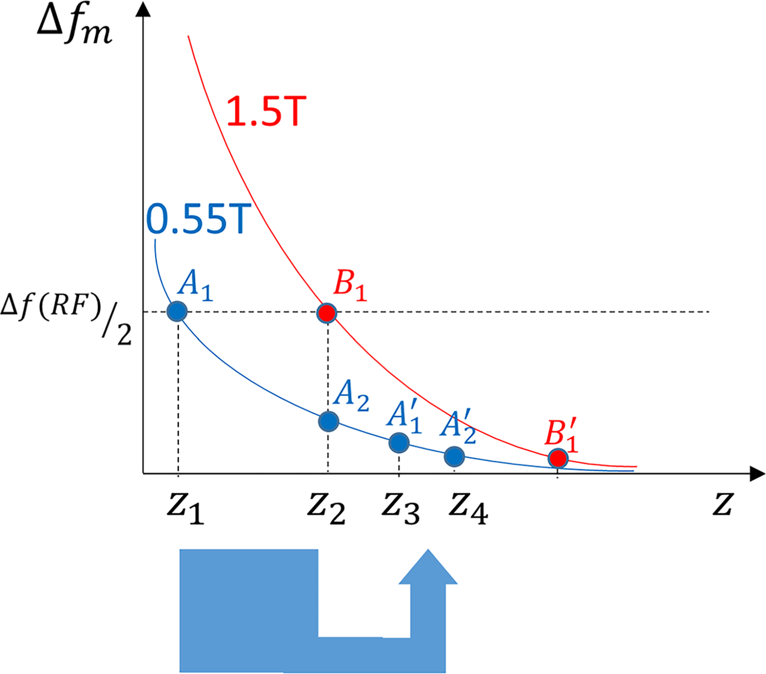
FIGURE 7.

Simplified model of metal-induced changes in the precession frequency (Δfm) as a function of distance from the metal surface (z) for 1.5 T (red) and 0.55 T (blue) field strengths. For similar RF pulse bandwidths (Δf(RF)), those spins outside the RF pulse bandwidth (z < z1 for 0.55 T and z < z2 for 1. 5 T) will not be excited, which explains the larger areas of signal loss due to off-resonance at 1.5 T. Through plane signal displacement for each excited point with a frequency offset of Δfm equals with γ representing the gyromagnetic ratio and Gss representing the slice-selection gradient. Whereas the signal displacement for points A1 at 0.55 T and B1 at 1.5 T are equal, the signal from points z1 < z < z2 at 0.55 T (not excited at 1.5 T) will be distorted (eg, compressed) into the adjacent slices and appear as signal pileups.
