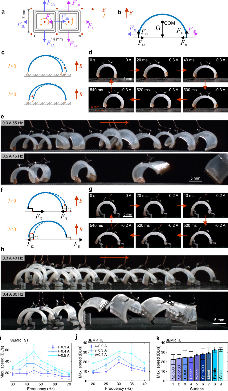
Fig. 3. Running mechanism and performance of SEMRs.
a Lorentz forces acting on the various parts of the liquid metal coils in the external magnetic field (), top view; current () is indicated by the counterclockwise arrows. The force pairs (, ) and (, ) are perpendicular to the bending direction and cancel. The central pair (, ) also cancels in the overall balance. b Free-body diagram of curved SEMR with the remaining relevant loading Lorentz forces (, ), side view. Gravity force () is applied to the center of mass (COM); the normal supporting forces (, ) and frictional forces (, ) are indicated as well. c Running mechanism of the SEMR TST on an asymmetrically structured substrate. d Key stages for the walking SEMR TST driven by a square-wave current (0.3 A, 1 Hz). e Snapshots of the running SEMR TSTS driven by square-wave currents (0.3 A, 55 Hz and 0.5 A, 45 Hz), as indicated. The time between the snapshots is 0.05 s. The bottom sequence corresponds to the maximum speed of 70 BL/s. f Running mechanism of the SEMR with the L-shaped feet. g Key stages for the walking SEMR TST driven by a square-wave current (0.2 A, 1 Hz). h Snapshots of the running SEMR TL driven by square-wave currents (0.3 A, 40 Hz and 0.4 A, 30 Hz), as indicated. The time between the snapshots is 0.05 s. The bottom sequence corresponds to the maximum speed of 35 BL/s. i Maximum speed of the SEMR TST driven by square-wave currents as a function of frequency at different amplitudes (0.3 A, 0.4 A and 0.5 A). j Maximum speed of the SEMR TL driven by square-wave currents as a function of frequency at different amplitudes (0.2 A, 0.3 A and 0.4 A). k Maximum running speed of SEMR TL on different substrates, including various sandpapers (Sp-p80, p180 and p400), elastomer (PDMS), paper, wood, metal, plastic and glass (Supplementary Movie 3). All error bars represent the standard deviation of four measurements. All snapshots are from different parts of Supplementary Movie 3.

