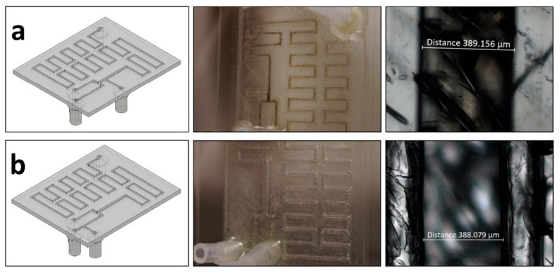
Figure 30.
(a) (Left) Bottom view of the device used to synthesize nanoparticles with the mineral oil inlet put after the reactants. (Center) Top view photograph of the actual microfluidic chip showing fouling along the channels. (Right) Optical microscopy of the bottom of the channel showing a darker color due to fouling. (b) (Left) Same as (a) but this device presents the mineral oil inlet between the reactants flows. (Center) Same as (a) but this device presents no fouling along the channels. (Right) Same as (a) but this time there is no darker coloration inside the channel due to fouling. Reprinted from an open-access source [103].

