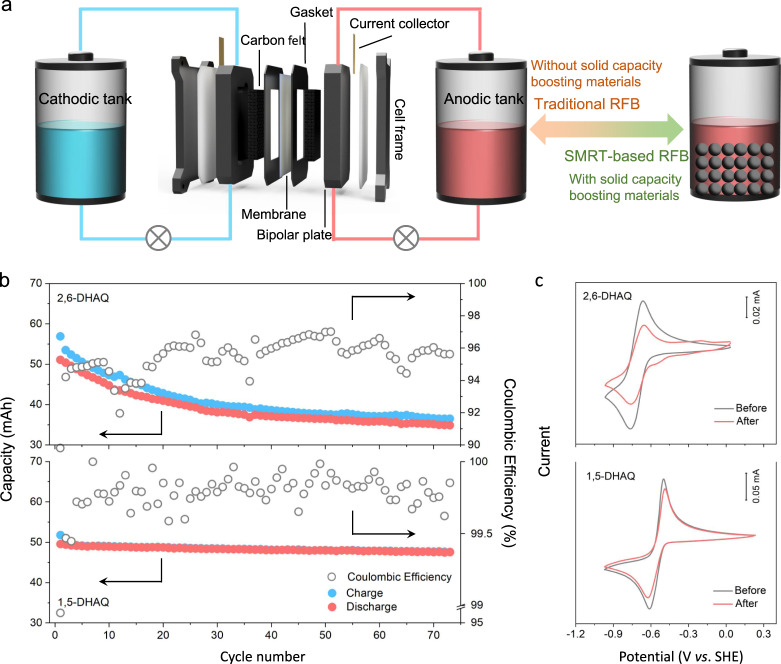
Fig. 3. Setup of the batteries and electrochemical performances of conventional RFBs.
a Schematic illustration of the configuration of a conventional RFB with liquid electrolytes filled in both tanks and that of a SMRT-based RFB with solid capacity-boosting material loaded in the anodic tank. The electrode active area was 5 cm2. b Coulombic efficiency and capacity retention for the anolyte-limited DHAQ|[Fe(CN)6]3−/4− full cells. The catholyte was 80 mL 0.25 M K4Fe(CN)6 + 0.05 M K3Fe(CN)6/1 M KOH; the anolyte was 10 mL 0.1 M 2,6-DHAQ or 1,5-DHAQ/1 M KOH. The current density was 20 mA/cm2. c CVs of 5 mM 2,6-DHAQ and 1,5-DHAQ diluted anolyte before and after cycling. The scan rate was 50 mV/s. All tests were conducted at 25 ± 1 °C.

