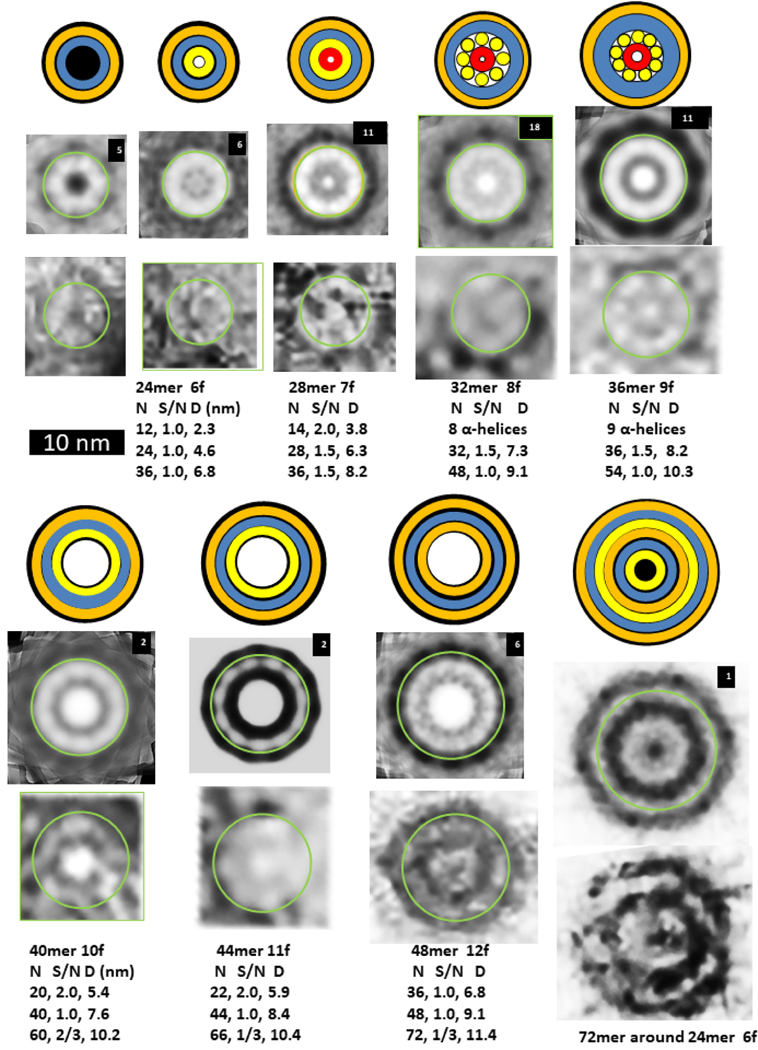
Figure 7.
Images of WCsAPFs and schematics of Aβ42 models with three concentric β-barrels. The outer orange rings of the schematics represent the outer β-barrel formed by S1 and S2, the blue ring represents a S3 β-barrel, the inner orange ring represents an inner β-barrel formed by S1 and S2, the inner yellow ring represents a β-barrel formed only by S2 strands, and the tiny red ring represents a highly tentative β-barrel formed by S1a segments. The yellow cylinders of the 32mer and 36mer models represent α-helices formed by S1b-S2 segments. Parameters of the models are listed below the images. The upper rows of images were averaged radially for the number of WCsAPF’s indicated in the upper right corner. The lower row of images are individual sAPFs. The green circles on the images indicate the proposed size and location of boundary between the outer and middle β-barrels. A small DCsAPF (the first image) was included because it also occurs frequently within the same region of the micrograph. The final schematic/EM image is larger and has more concentric rings than the others. The schematic illustrates that the assembly may have six concentric β-barrels with a three-barrel 72mer sAPF surrounding a three-barrel 24mer sAPF (also see Supplement Fig. S5).

