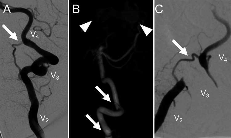
FIG. 1.
Left VA injection (A) prior to head rotation for craniotomy. Normal flow is seen in V2, V3, and V4 segments, and a prominent muscular branch (white arrow) is noted. 3D DSA of left VA injection (B) shows a multihole pial AVF (white arrowheads) and demonstrates that the presumed muscular branch (white arrows) connects the V2 and V4 segments. Intraoperative left VA injection with head rotation for the transcallosal approach (C) shows occlusion of the V3 segment with “jump” collateral filling of V4 via the collateral branch (white arrow).

