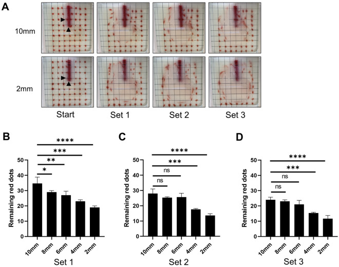
Figure 6.
Flow visualization. Modified NC with side holes made at 2, 4, 6, 8, or 10 mm from the tips were used. (A) Red dots were drawn on the inside of the front wall of the container to match the intersections of the grid. Images before and after each set using the modified NC with side holes at 2 or 10 mm from the tips under 20 mm/s are shown. Black arrows indicate the location of each hole. (B–D) The number of red dots remained in the original position were compared between modified NCs after each set.

