
Figure 2.
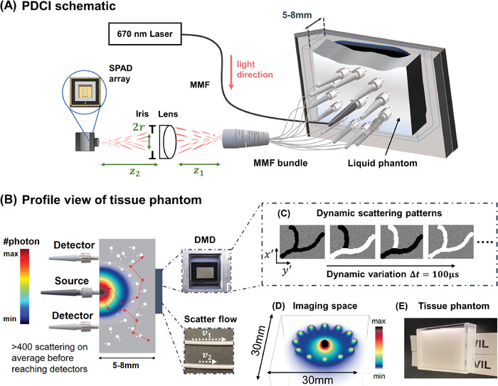
A) Schematic of PaDI system for imaging decorrelation. Back‐scattered coherent light from single input port is collected by 12 multimode fibers (MMF) at tissue phantom surface and guided to SPAD array camera. B) Profile view of the tissue phantom imaging experiment. Digital micro‐mirror device (DMD) and vessel phantom serve as source of temporal dynamics and is hidden beneath phantom by placing it immediately adjacent (separated by coverglass). All sources and detectors are placed on the same side of phantom. Colormap provides qualitative photon distribution map, where quantitative plot of sub‐surface photon distribution is in Figure S1B, Supporting Information. C) A set of DMD patterns that can be used to generate spatiotemporal varying dynamics. (D) Simulation of photon‐sensitive region of our 12‐fiber system. (E) A picture of the tissue phantom we use in experiments.