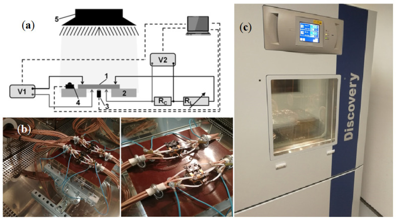
Figure 19.
Silicon samples laboratory stand. (a) Schematic diagram of the laboratory stand: 1—solar cell, 2—supporting construction, 3—temperature sensor, 4—pyranometer, 5—light source, V1—Fluke 289, V2—The LCR-8110G Series LCR meter, RC—shunt resistor, RL—adjustable load. (b) Special measuring holders inside the climate chamber to hold silicon samples. (c) Discovery DY600C climate chamber [90].

