. 2022 Apr 27;4(10):2242–2249. doi: 10.1039/d2na00032f

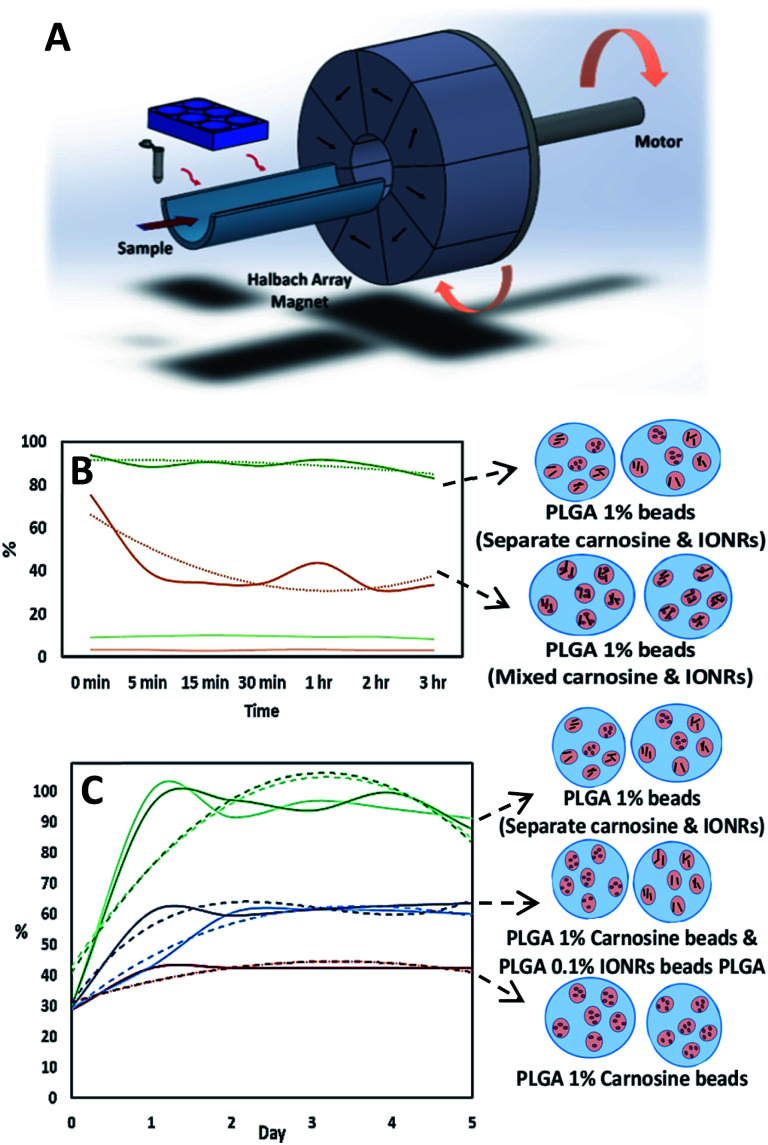
Fig. 6. (A) Schematic illustration for the rotating magnet system designed for this application. The arrows indicate the direction of the magnetic field which produce an intense uniform magnetic field within their central air gap, and zero field outside. (B) LC-MS assay for the normalised concentrations of carnosine show the advantage of using the hydrophobic chip (dark curves) the hydrophilic chip (light curves) for the initial emulsification. (C) LC-MS assay for the normalised concentrations of carnosine show the comparison between adding the encapsulated IONRs to the carnosine before or after the initial emulsification. Curves with light colours are for beads before the application of magnetic field and the curves with dark colours are for after the application of magnetic field. Red spheres are carnosine and black rods are IONRs. The dotted lines are trend lines fitted to the normalised concentration of the released carnosine.

Fig. 6