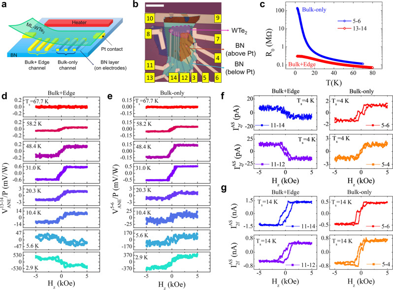
Fig. 3. Anomalous Nernst effect and anomalous Hall effect from edge and bulk channels of ML-WTe2/Cr2Ge2Te6.
a Schematic diagram of device structure. Electrodes on the left side probe combined edge and bulk signal of ML-WTe2, and those on the right side are partly covered with BN to prevent edge contact with ML-WTe2, thus only detect the bulk ANE. b Optical image of device D7 prior to transfer of ML-WTe2/Cr2Ge2Te6 composite layer. The ML-WTe2 flake is indicated by the purple dashed polygon. Electrodes from 11 to14 probe the ANE signal from both edge and bulk, and electrodes from 3 to 6 probe the bulk-only ANE signal. The scale bar is 10 . c Temperature dependence of resistance from 5–6 (Bulk) and 13-14 (Bulk + Edge). d, e ANE signals from 13–14 (d) and 5–6 (e) at selected temperatures. For Ts < 20 K, 40 loops are used for averaging; for Ts > 20 K, 20 loops are used for averaging. f, g 2 f current response from Bulk + Edge (11–14 and 11–12) and Bulk-only (5–6 and 5-4) channels to AC voltage applied between the two outermost horizontal electrodes on ML-WTe2 vs. Hz at Ts = 4 K (f) and 14 K (g). 60 loops are used for averaging in f, and 10 loops for other curves than the 11–14 electrodes (3 loops) in g, respectively. The rms magnitudes of the AC voltage for 4 K and 14 K measurements are 20 and 200 mV, respectively.

