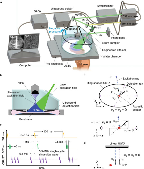
Figure 1.

CRUST‐PAT implementation. a) Perspective view of the CRUST‐PAT system. b) Cut‐away view showing the ultrasound excitation, PA excitation, and acoustic detection fields. c) Perspective view (top) and side view (bottom) of CRUST for flow imaging. S, the position of the VPS; T, the position of the acoustic scatterer; v, blood flow velocity in the xz plane; vST , velocity projection coefficient along the excitation ray; v 1–v 4, velocity projection coefficients along the detection rays. Even for flow velocity with equal projection coefficients along the excitation and detection rays (i.e., − vST + v 3 = 0), there always exist nonzero projection coefficients along other detection rays (e.g., v 1 ≠ 0). d) Conventional Doppler ultrasound imaging of the blood flow. e) Excitation sequences of CRUST and PAT.
