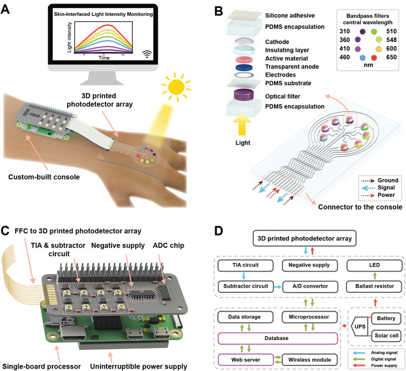
Figure 1.

Skin‐interfaced photodetector system for in‐situ light intensity monitoring. A) Schematic illustration of the photodetector array with a console in operation. The system consists of a photodetector array for monitoring the light intensity of eight different wavelengths and a custom‐built console for signal processing and wireless data transmission. B) Schematic of the 3D printed photodetector array. The photodetectors and optical filters with eight different central wavelengths are assembled on the top and backside of the flexible polydimethylsiloxane (PDMS) substrate, respectively. The left inset is an exploded view of one photodetector with an optical bandpass filter. The right inset is the positioning of the central wavelengths of the optical bandpass filters. C) Schematic of the console for the monitoring system. The console consists of a custom‐built signal processing board for driving photodetectors and processing photocurrent signals, a single‐board processor for data processing and transmission, and an uninterruptable power supply (UPS) module for power management. D) Schematic block diagram of the monitoring system.
