Fig. 3.
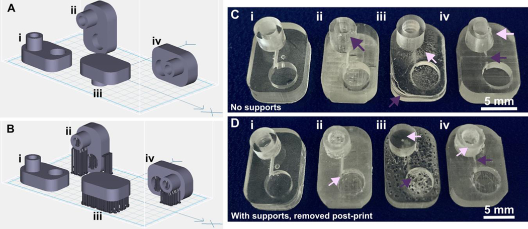
Orientation of prints on a build plate impacts the print resolution and optical clarity. A microfluidic design containing a reservoir, channel, and chamber is shown in the MiiCraft Utility slicing software in four orientations (A) without supports and (B) with supports: (i) base-down, (ii) vertical, (iii) top-down, and (iv) horizontal. Blue grid represents the base plate. Supports were added to all areas using default settings in the slicing software. (C, D) Photos of pieces printed in BV007a resin with the MiiCraft Ultra 50 printer, (C) printed without supports, and (D) printed with supports, with 2 minutes of support removal. Surface roughness and clarity variation is evident between the 4 orientations. Defects were noted as follows: In C: (i) no defects, (ii) overhang drooping, (iii) delamination (purple) and stress fracturing (pink), (iv) blocked channel (purple), overhang drooping (pink); in D: (i) no defects, (ii) stress fracturing, (iii) damage from supports (purple) and filled chamber (pink), (iv) filled channel (purple) and support damage (pink).

