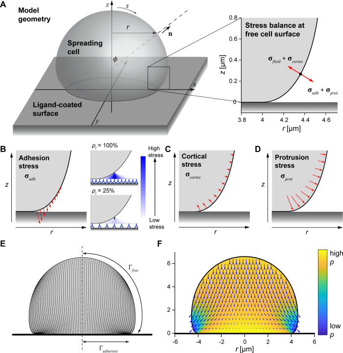
Fig 1. Illustration of our computational model of isotropic cell spreading.
(A) 3D rendering shows the geometry and defines coordinates for an axisymmetric spreading cell on a flat surface. The enlarged inset (right) illustrates the stress balance at the free cell boundary. (B) Pre-contact adhesion stress effectively pulls the membrane onto the flat surface. The enlarged insets conceptually depict how the adhesion stress is computed for different ligand densities ρl. (C) Cortical tension and membrane curvature give rise to an effective inward normal stress. (D) The protrusion stress acts normal to the cell membrane and is concentrated at the region of the membrane closest to the substrate. (E) The cross-sectional snapshot of a simulation illustrates the mesh composed of quadrilateral elements used in the calculations, with tighter element packing closer to the flat surface. The computational domain only includes half of this mesh due to axial symmetry. Boundary regions are labeled Γ, and the vertical dashed line is the symmetry axis (r = 0) (F) This snapshot of a simulation illustrates the fluid velocity (vector field) and relative pressure (heat map) computed for a given cell shape with known boundary stresses.

