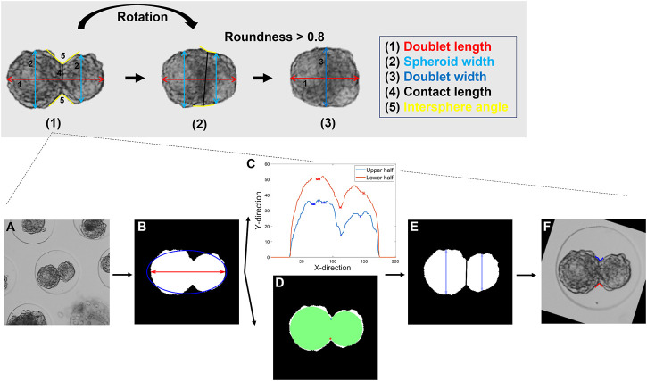
FIGURE 3.
Description of the feature extraction procedure. Top panel: Visualization of the three different stages of the feature extraction with (1) the initialization for frame 1 and the subsequent feature extraction (2) before and (3) after a doublet roundness of 0.8 was reached. Bottom panel: Detailed representation of stage (1). (A) Raw image. (B) Segmented mask. The doublet area, length, and roundness were extracted. (C) Profile of the upper and lower half of the doublet with the detected minima. (D) Alternative method for the detection of the spheroid’s interface based on two maximally inscribed circles. (E) A cost function was defined to select the appropriate profile points. The spheroids were separated, and the contact length and both spheroid widths computed. (F) Upper and lower intersphere angles were extracted. (2) For subsequent frames, the same features as in (1) were extracted, and the rotation of the doublet with respect to the previous frame was determined. (3) As previously described, the mask was aligned with the horizontal axis. The doublet area, length, and width were extracted. More details on the features and the feature extraction are listed in the supplementary information (details on Panel 3 or Supplementary Table S2).

